
Concurrent operation of a state machine family

A technology of state machine and master state machine, applied in the field of telecommunications

Inactive Publication Date: 2005-12-28
NOKIA SOLUTIONS & NETWORKS OY
View PDF1 Cites 2 Cited by
  • Summary
  • Abstract
  • Description
  • Claims
  • Application Information

AI Technical Summary

Problems solved by technology

[0011] However, as is evident from the above, this mechanism has significant drawbacks

Method used


Image

  • Concurrent operation of a state machine family
  • Concurrent operation of a state machine family

Examples


Embodiment Construction

[0032] Reference will now be made in detail to embodiments of the invention, examples of which are illustrated in the accompanying drawings.

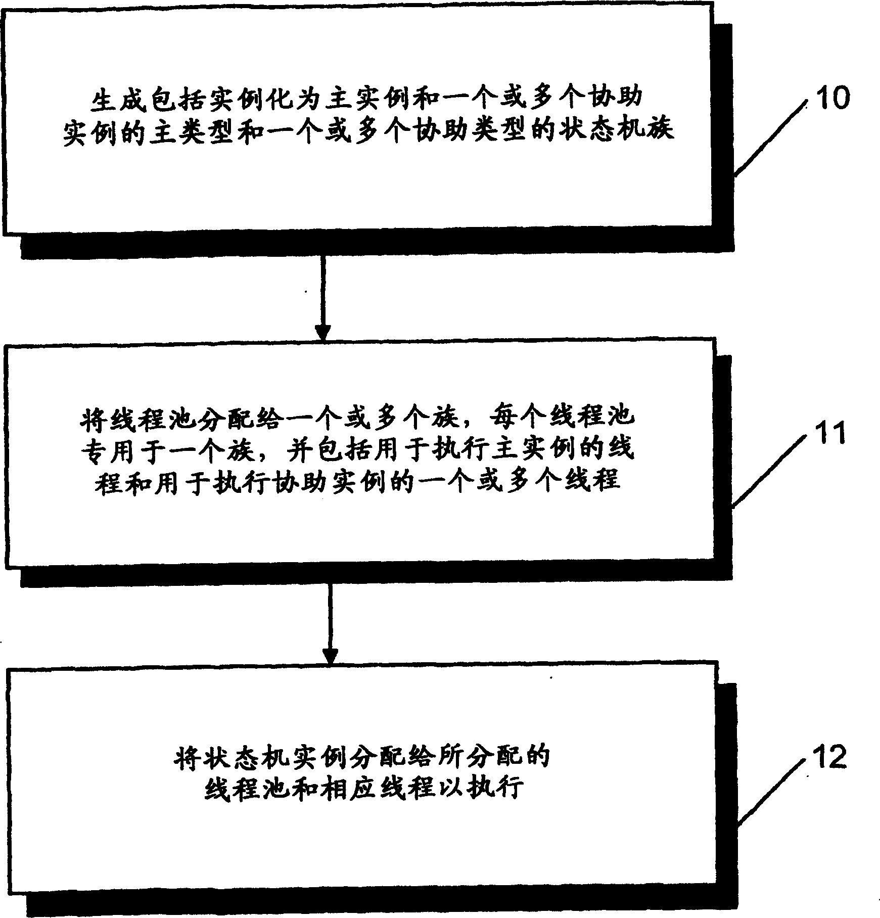
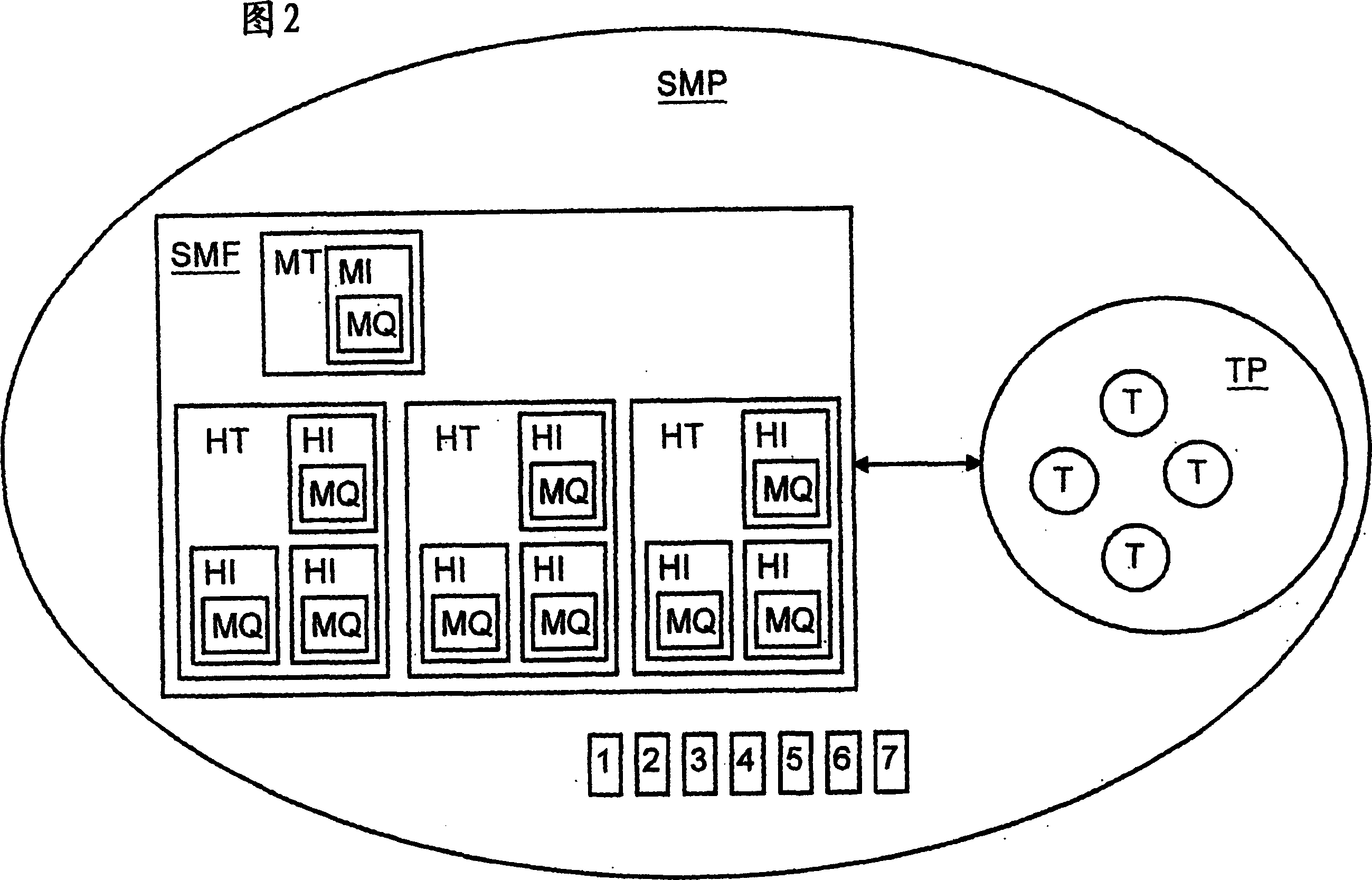
[0033] figure 1 A method of concurrently operating a state machine within a computing system is illustrated. Phase 10, generating one or more state machine families. Each family includes a master state machine type for receiving service requests from outside its family and for forwarding received service requests for servicing, and one or more assist states for receiving and servicing forwarded service requests machine type. The assistance state machine type can then communicate directly with the service requester. The main state machine type instantiates as a main instance and at least one helper state machine type instantiates as one or more helper instances. Each primary and secondary instance has its own message queue.

[0034] Phase 11, assigning thread pools to one or more generated state machine families. Each thread pool i...


PUM


Abstract

The present invention relates to a method and system for concurrently operating state machines within a computing system. Generate one or more state machine families. Each family includes a master state machine type for receiving service requests from outside the family and forwarding received service requests for servicing, and one or more assist state machine types for receiving and servicing forwarded service requests. Assign thread pools to one or more state machine families. Each thread pool is dedicated to a state machine family and includes one or more threads for executing the master and helper instances of the corresponding state machine family. One or more state machine instances of the generated state machine family are assigned to corresponding threads of the assigned thread pool for execution.

Description

technical field [0001] This invention relates to telecommunications. In particular, the present invention relates to new and improved methods and systems for concurrently operating state machines within a computing system. Background technique [0002] Software applications typically use state machines that interact by passing messages. A state machine is a software component that maintains data that defines its state between its inputs, such as messages from other state machines or from the operating system, and whose behavior at any given time in response to received input depends on its state. In telecommunications, input is usually received as asynchronous messages. The reason for the popularity of state machines is that state automata have proven to be a powerful software engineering method when implementing signaling applications in telecommunications. Due to the message-oriented nature of asynchronous signaling applications, it is natural to implement them as state...

Claims


Application Information

Patent Timeline
Patent Type & Authority Applications(China)
IPC IPC(8): G06F7/00G06F9/00G06F9/46G06F17/30
CPCG06F9/5027G06F2209/5011Y10S707/99931
Inventor 尤哈·柳科宁尤卡·西尔亚宁雅尔莫·鲁夏拉托米·卡特萨罗欧基·鲁奥图拉马库斯·马尔姆克维斯特
Owner NOKIA SOLUTIONS & NETWORKS OY
Learn More