Microchannel plate having microchannels with deep funneled and/or step funneled openings and method of manufacturing same

A micro-channel plate and micro-channel technology, applied in the field of micro-channel plates with micro-channels, can solve the problems of reduced collection efficiency, reduced signal-to-noise ratio, reduced performance of image intensifier tubes, etc.

Inactive Publication Date: 2006-01-04
EXCELIS INC
View PDF1 Cites 17 Cited by
  • Summary
  • Abstract
  • Description
  • Claims
  • Application Information

AI Technical Summary

Problems solved by technology

The reduction in the collection efficiency of the input electrons also degrades the performance of the image intensifier tube by reducing its signal-to-noise ratio

Method used


Image

  • Microchannel plate having microchannels with deep funneled and/or step funneled openings and method of manufacturing same
  • Microchannel plate having microchannels with deep funneled and/or step funneled openings and method of manufacturing same
  • Microchannel plate having microchannels with deep funneled and/or step funneled openings and method of manufacturing same

Examples


Embodiment Construction

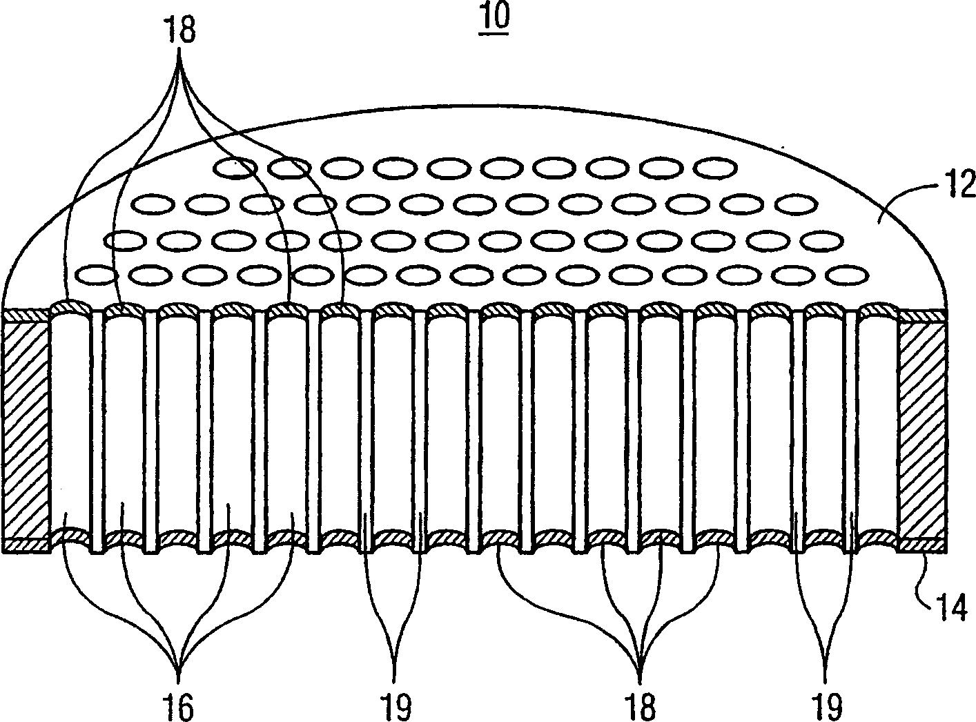
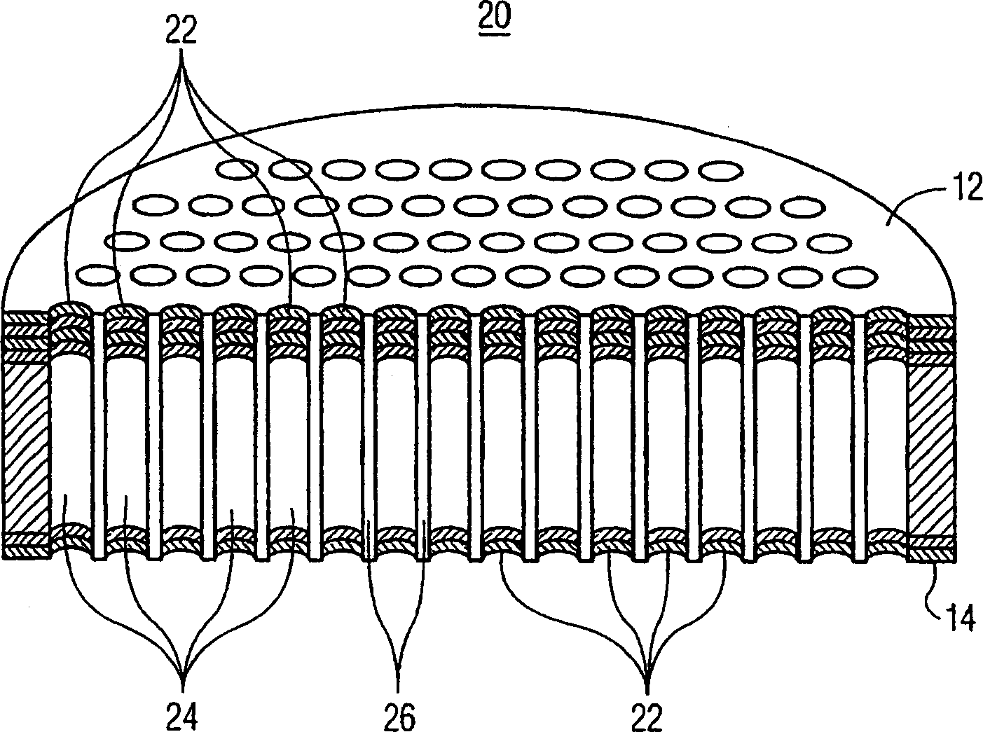
[0029] In accordance with the present invention, a microchannel plate (MCP) with deep funnel-shaped openings and / or stepped funnel-shaped openings overcomes the drawbacks due to metallization of exposed microchannels on the input side or output side. By moving the funnel deeper into the MCP microchannel (or further away from the input / output side), the performance of the MCP is improved without performance degradation due to any metallization process. Incident electrons are less prone to hitting metal coatings located in deep funnel channels, as they may be located in perfectly straight channels of the same diameter.

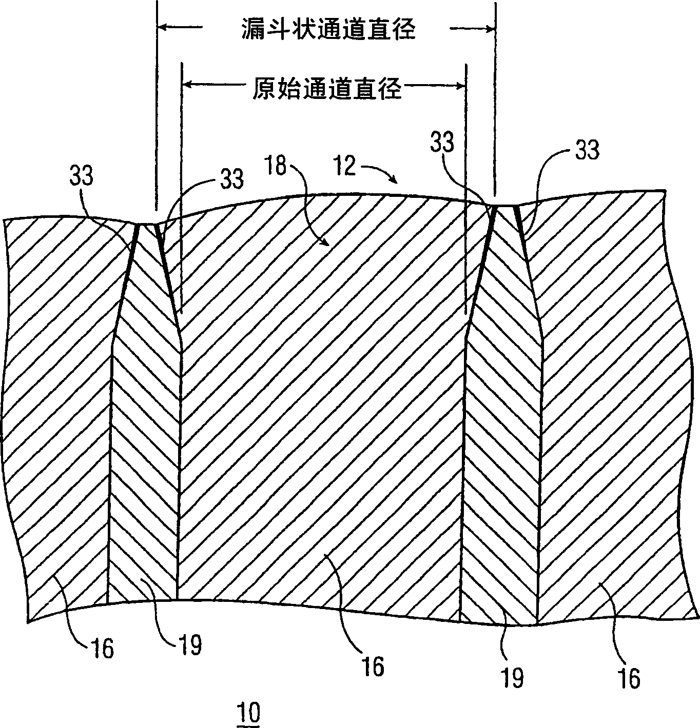
[0030] Additionally, while deep funnel-shaped channels have a wider diameter than non-funnel-shaped channels or substantially funnel-shaped channels (basic funnel-shaped channels as disclosed in US Pat. 90% of its length) with sufficient wall thickness and provide sufficient strength and stiffness to the MCP.

[0031] refer to Figure 1B , which shows a cross-...


PUM


Abstract

The invention includes a microchannel plate for an image intensifier tube, in which the plate has multiple microchannels extending in a longitudinal dimension between transverse surfaces of the plate. Each microchannel includes a first portion forming a first opening at an end proximate a surface of the plate. The first portion includes a wall extending longitudinally from the surface and terminating in a substantially similar first opening at a distal end. The microchannel also includes a second portion of the wall, extending longitudinally from the first opening at the distal end and tapering toward a second opening at a further distal end. The first opening at the proximate end has a diameter that is substantially similar to a diameter of the first opening at the distal end. The first opening is also wider than the second opening.

Description

technical field [0001] The present invention generally relates to a microchannel plate for use in an image intensifier tube, and more particularly to a microchannel plate having microchannels with deep funnel-like openings and / or stepped funnel-like openings. Background technique [0002] Image intensifier tubes are used in night / low light situations to amplify ambient light into useful images. A typical image intensifier tube is a vacuum device that is roughly cylindrical in shape and typically includes a body, photocathode and faceplate, a microchannel plate (MCP) and output optics and a phosphor screen. The incoming photons are focused on the glass panel by external optics and impinge on a photocathode bonded to the inner surface of the panel. The photocathode converts photons into electrons, which are accelerated toward the MCP by the electric field. The MCP has a number of microchannels, each of which acts as an independent electronic amplifier and basically correspon...

Claims


Application Information

Patent Timeline
Patent Type & Authority Applications(China)
IPC IPC(8): H01J43/24H01J9/12G02B6/08
CPCG02B6/08H01J31/507H01J43/246
Inventor 史蒂文·戴维·罗西纳纳尔逊·克里斯托弗·德沃
Owner EXCELIS INC
Why Eureka
Try Eureka