Fastener
A technology of fasteners and components, applied in the direction of rivets, etc., can solve the problems of inability to apply large clamping force and weakening of clamping force.
- Summary
- Abstract
- Description
- Claims
- Application Information
AI Technical Summary
Problems solved by technology
Method used
Image
Examples
Embodiment 1
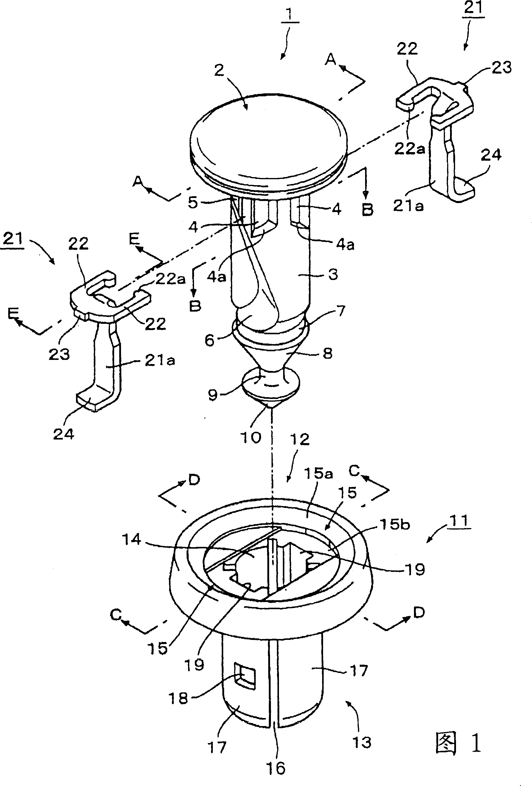
[0057] The present invention will be described based on the following preferred embodiment. Unlike the fastener of the prior art, as shown in FIG. 1, the fastener according to this embodiment includes three parts, namely, a pin made of synthetic resin 1. A grommet 11 made of synthetic resin and a clamp member 21 made of metal, and characterized in that each part 1, 11, 21 adopts the following structure. In addition, for clamp members made of metal, the clamp members 21 are used in a paired relationship.
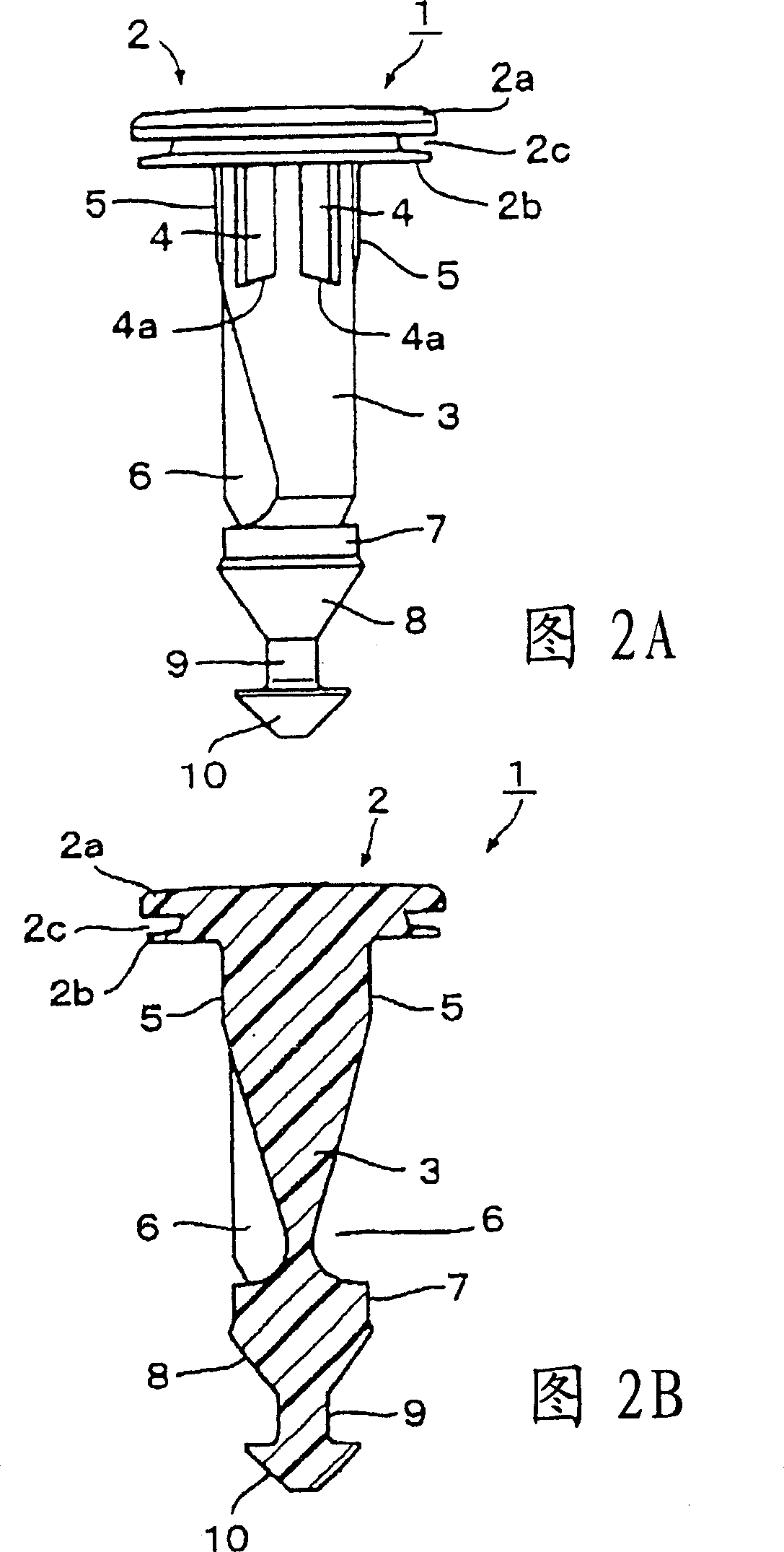
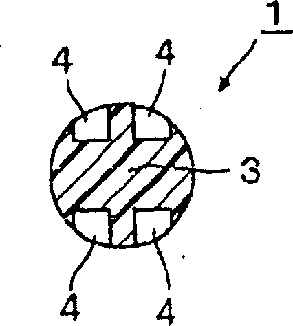
[0058] Therefore, firstly, a pin 1 made of synthetic resin will be described, and as also shown in FIGS. It includes a thick-walled upper plate 2a and a thin-walled lower plate 2b, and is separated by a ring-shaped insertion groove 2c so that the front end of the tool is inserted between the upper plate 2a and the lower plate 2b, and the rear rod 3 member Consisting of a structure in which support grooves 4 are formed on one side of the upper side opposite to each other, and...
Embodiment 2
[0074] The fastener of the second embodiment is explained below, although the structure of the second embodiment basically follows the structure of the above-mentioned first embodiment, the difference between the two lies in the structure in which from the shank 3 of the pin 1 A pair of anti-movement walls 30 in a state parallel to each other protrude integrally from both side edges of the two accommodating chambers 6 formed on the side, on the sides of the support groove 4 of the lower plate 2b constituting the head 2 of the pin 1 The peripheral edge existing on the top is cut by a notch 31 , and a protruding stripe 32 parallel to the edge of the notch 31 is provided on the upper plate 2 a at a position directly above the edge of the notch 31 .
[0075] Therefore, according to the second embodiment, by the presence of the aforementioned pair of movement preventing walls 30, when the clamping member 21 is supported by the shank portion 3 of the pin 1 and inserted into the cylin...
Embodiment 3
[0079] In the following, the present invention will be described in detail according to preferred embodiments, and the difference from the fasteners of the background art is, for example Figure 11 As shown, the fastener of this embodiment includes three parts: a pin 101 made of synthetic resin, a grommet 111 made of synthetic resin, and a clamping member 121 made of metal, characterized in that Each section 101, 111 and 121 adopts the following structure. In addition, as for the clamp member made of metal, the clamp member 121 is formed of a low-rigidity elastic metal plate and used in pairs.
[0080] Therefore, first, the explanation starts from the pin 101 made of synthetic resin, as Figure 12 As shown, the pin 101 is provided with a disc-shaped head 102 and a cylindrical stem 103. Specifically, the latter stem 103 is structured as follows, wherein a pair of opposite sides of the upper part are formed. The pressing surface 104 is used to press the outwardly guiding clamp...
PUM
 Abstract
Description
Claims
Application Information
 - R&D
- Intellectual Property
- Life Sciences
- Materials
- Tech Scout
- Unparalleled Data Quality
- Higher Quality Content
- 60% Fewer Hallucinations
Browse by: Latest US Patents, China's latest patents, Technical Efficacy Thesaurus, Application Domain, Technology Topic, Popular Technical Reports.
© 2025 PatSnap. All rights reserved.Legal|Privacy policy|Modern Slavery Act Transparency Statement|Sitemap|About US| Contact US: help@patsnap.com


