Check patentability & draft patents in minutes with Patsnap Eureka AI!

Backlight module

A technology of backlight module and light guide plate, applied in optics, nonlinear optics, instruments, etc., can solve the problems of high manufacturing difficulty, uneven brightness, and high cost, achieve uniform brightness, improve brightness uniformity, reduce manufacturing costs and The effect of making difficulty

Inactive Publication Date: 2006-01-18
HONG FU JIN PRECISION IND (SHENZHEN) CO LTD +1
View PDF1 Cites 3 Cited by
  • Summary
  • Abstract
  • Description
  • Claims
  • Application Information

AI Technical Summary

Problems solved by technology

[0005] In order to overcome the problems of uneven brightness, high manufacturing difficulty and high cost of the prior art backlight module, the present invention provides four backlight modules with uniform brightness, simple manufacture and low cost.

Method used


Image

  • Backlight module
  • Backlight module
  • Backlight module

Examples


Embodiment Construction

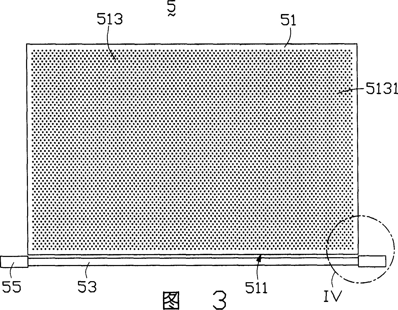
[0018] See Figure 3 and Figure 4 , is a plan view and a partially enlarged view of the first embodiment of the backlight module of the present invention. The backlight module 5 of the first embodiment includes a light guide plate 51 and a light tube 53 . Both ends of the lamp tube 53 are provided with power connection portions 55 for connecting to a power source. The light guide plate 51 is square in shape and includes a light incident surface 511 , a light exit surface 513 and a bottom surface (not shown) opposite to the light exit surface 513 . The surface of the light-emitting surface 511 of the light guide plate 51 is provided with grid dots 5131 for diffusing light beams, and the grid dots 5131 are evenly divided into the light-emitting surface 513 of the light guide plate 51 .

[0019] The light tube 53 is disposed on the light incident surface 511 side of the light guide plate 51 to provide light beams for the light guide plate 51 . Two ends of the lamp tube 53 are ...


PUM


Abstract

The invention discloses a phototropic mold train, which comprises a light driving plate and a lamp pipe. The light driving plate comprises a light inlet side, a base side and a light outlet side, wherein the lamp pipe is opposed disposed with the light inlet side; the two ends of the lamp pipe have the connecting part which is used to connect power; the connecting part is positioned on the out side of the light inlet side, so that the luminous area beam of lamp pipe can inlet the corner of the light driving plate.

Description

【Technical field】 [0001] The invention relates to a backlight module for providing a surface light source for a liquid crystal display. 【Background technique】 [0002] Liquid crystal display is a non-self-illuminating display device, and its display is mainly realized by controlling the passage or non-passing of the light beam emitted by the external light source. Therefore, an external light source and a corresponding light guide device are required. The beam guides the display panel. [0003] see figure 1 and figure 2 , is a backlight module disclosed in Japanese Patent Application No. H11-207553 published on February 9, 2001. The backlight module 1 includes a lamp tube 11 and a light guide plate 13 . The light guide plate 13 includes a light incident surface 131 , a light exit surface 133 , and a bottom surface (not shown) opposite to the light exit surface 133 . The light exit surface 133 is provided with a plurality of dots 135 . The light beam emitted by the light...

Claims


Application Information

Patent Timeline
Patent Type & Authority Applications(China)
IPC IPC(8): G02F1/13357G02F1/133G02F1/1335
Inventor 陈弥坚陈云彰
Owner HONG FU JIN PRECISION IND (SHENZHEN) CO LTD
Features
  • R&D
  • Intellectual Property
  • Life Sciences
  • Materials
  • Tech Scout
  • Unparalleled Data Quality
  • Higher Quality Content
  • 60% Fewer Hallucinations
Learn More