Electric fan for vehicle use

一种车辆、电扇的技术,应用在电动组件、机电装置、电气元件等方向,能够解决电机冷却性能降低等问题

Inactive Publication Date: 2006-01-18
ASMO CO LTD
View PDF0 Cites 10 Cited by
  • Summary
  • Abstract
  • Description
  • Claims
  • Application Information

AI Technical Summary

Problems solved by technology

Correspondingly, the cooling performance of the motor is reduced

Method used


Image

  • Electric fan for vehicle use
  • Electric fan for vehicle use
  • Electric fan for vehicle use

Examples


Embodiment Construction

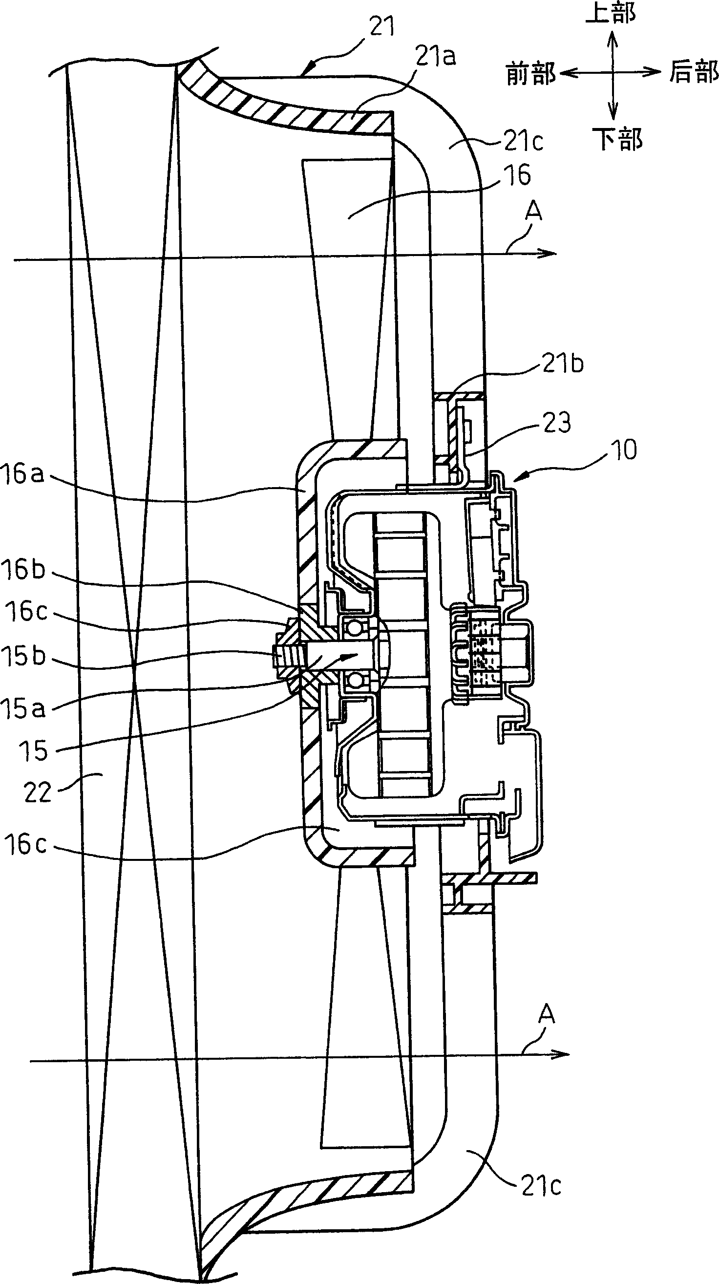
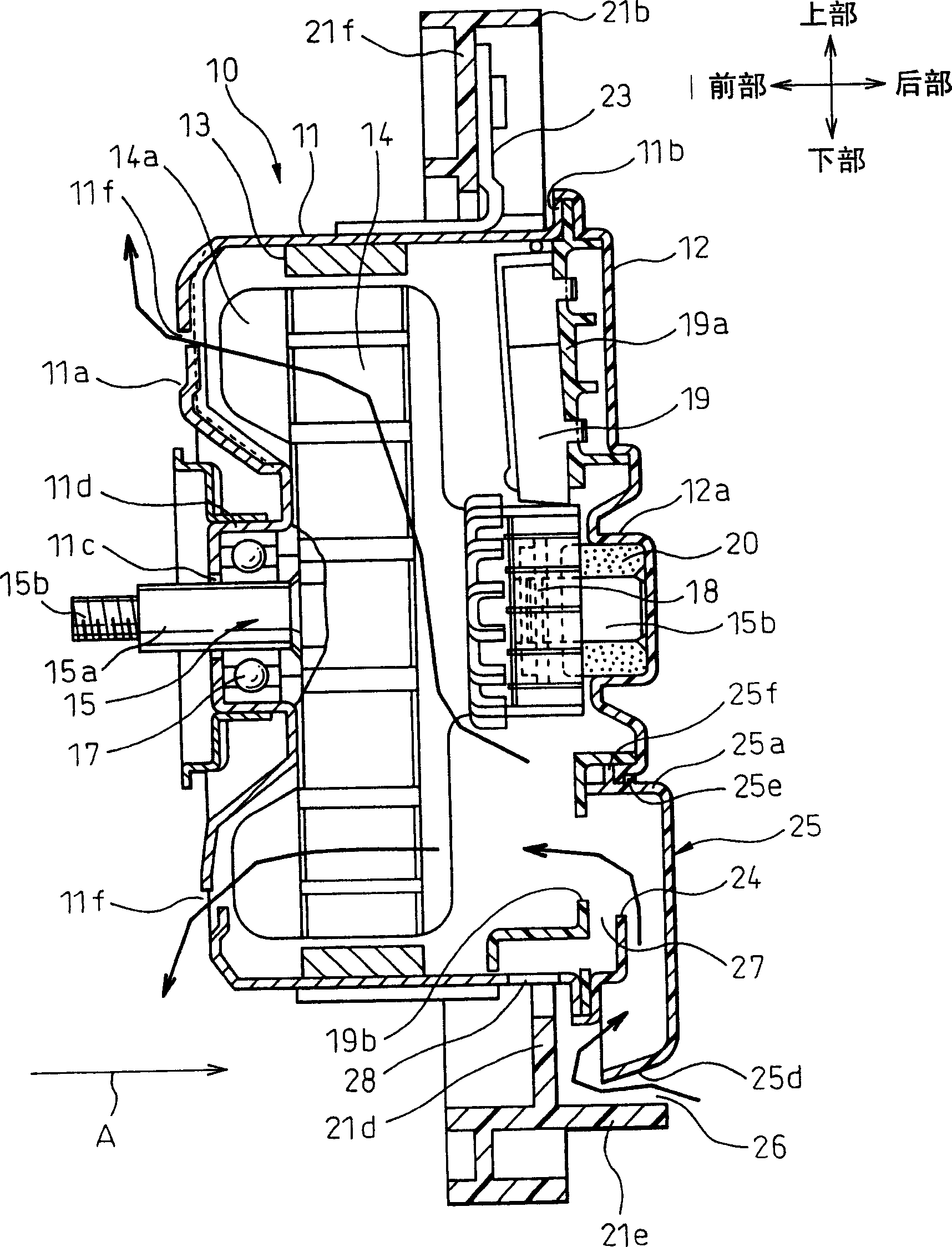
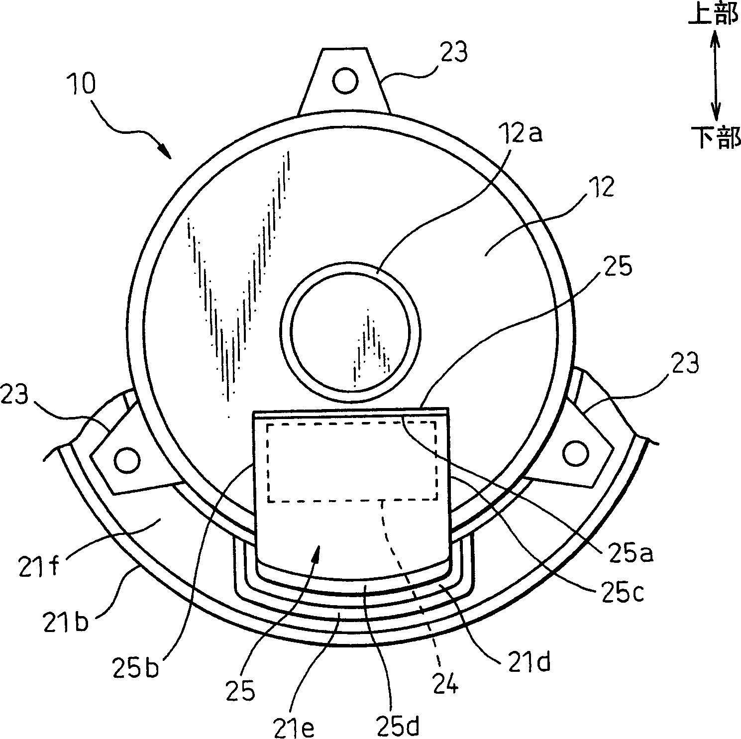
[0044] First, a first embodiment of the present invention will be described below. Figure 1-4 is a view showing the first embodiment of the present invention. figure 1 is a cross-sectional view showing the entire arrangement of the electric fan device used in the first embodiment of the present invention, figure 2 yes figure 1 An enlarged cross-sectional view of the motor portion of the, image 3 yes figure 2 right view of the Figure 4 is displayed figure 2An enlarged view of the main part of . In this connection, arrows up, down, front, and back in the drawings indicate directions in a case where the electric fan for a vehicle of the present invention is mounted on a vehicle.

[0045] exist figure 1 , 2 In this case, the motor 10 for driving the fan is mounted on the vehicle so that the axial direction of the fan can be directed in the longitudinal direction (horizontal direction) of the vehicle. The motor (10) for driving the fan comprises a cylindrical body ho...


PUM


Abstract

The cooling air introducing port 24 is open to a lower portion of an axial direction end portion of the motor housing member 11, 12, the water-proof cover 25 for covering the cooling air introducing port 24 is attached to the outside of the axial direction end portion of the housing member 11, 12, and the air introducing passage 26 having a labyrinth structure is composed of the bent portion 25 d provided in a lower end portion of the water-proof cover 25, the first wall face 21 d provided in the annular portion 21 b of the shroud and the second wall face 21 e.

Description

technical field [0001] The invention relates to an electric fan for moving air to the radiator of a vehicle. More particularly, the present invention relates to a structure for introducing cooling air into a motor for driving a fan. Background technique [0002] As a device for introducing cooling air into a motor for driving a fan, the device described in the official gazette of JP-A-9-74718 is known. [0003] According to the above-mentioned patent document, the cooling air introduction port (directed downward) is formed in the end portion of the end housing of the motor for driving the fan. In addition, first to third labyrinth plates are provided in the passage from the cooling air introduction port to the inside of the motor. [0004] The first labyrinth airtight barrier is in contact with and fixed to the cylindrical body case of the motor, and is directed in a direction substantially perpendicular to the horizontal direction when the motor is mounted on the vehicle....

Claims


Application Information

Patent Timeline
Patent Type & Authority Applications(China)
IPC IPC(8): H02K9/26H02K5/10H02K5/20H02K9/06
CPCH02K5/10H02K5/20F04D25/082H02K5/207F04D29/5806F04D29/706H02K9/26
Inventor 竹内和宏织田信一熊木宪治谷野利弘铃木伸哉
Owner ASMO CO LTD
Why Eureka
Try Eureka