Backlight module structure
A backlight module, recessed structure technology, applied in optics, nonlinear optics, instruments, etc., can solve the problems of uneven brightness, poor picture quality, and inability to use light effectively in liquid crystal displays
- Summary
- Abstract
- Description
- Claims
- Application Information
AI Technical Summary
Problems solved by technology
Method used
Image

Examples
Embodiment Construction
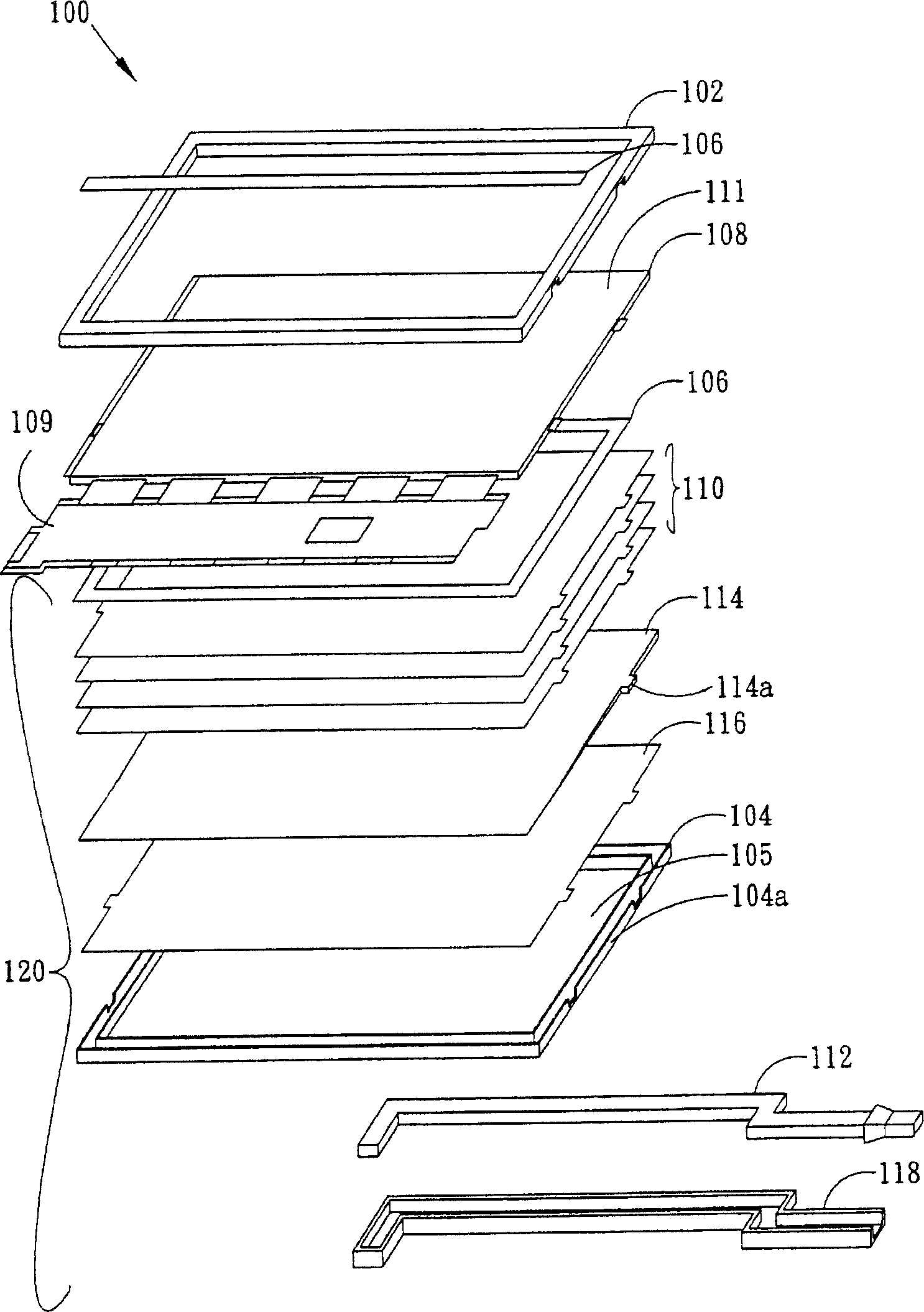
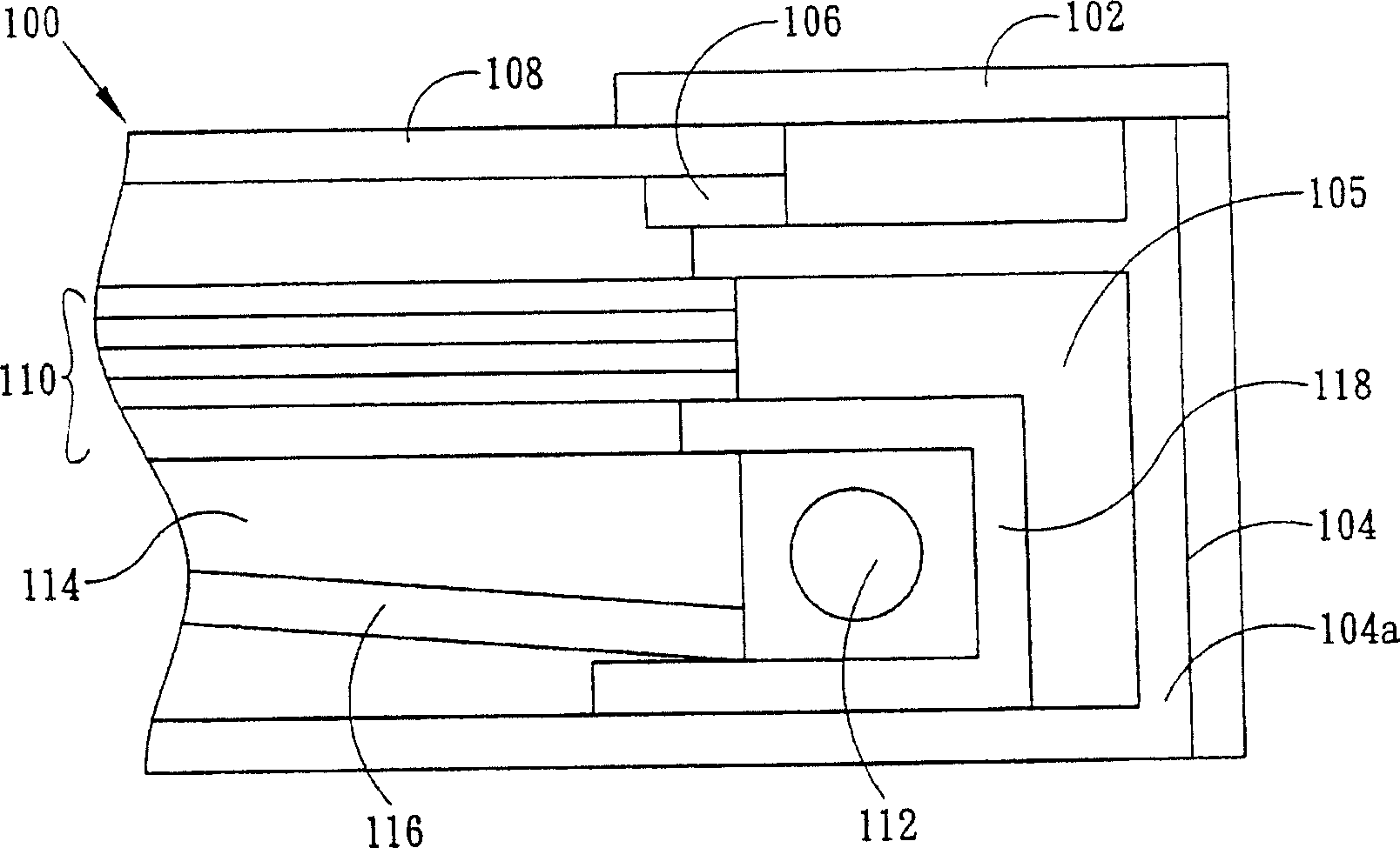
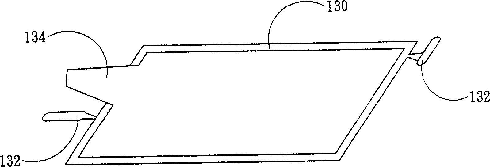
[0014] Some embodiments of the invention are described in detail below. However, the invention can be broadly practiced in other embodiments than this detailed description. That is, the scope of the present invention is not limited by the presented embodiments, but by the present claims. Secondly, when each component or structure in the diagrams of the embodiments of the present invention is described as a single component or structure, it should not be regarded as a limited cognition, that is, when the following description does not particularly emphasize the limitation on the number, the present invention The spirit and scope of application can be extended to structures and methods in which multiple components or structures coexist. Furthermore, in this specification, different parts of each component are not drawn to scale. Certain dimensions have been exaggerated or simplified compared to other relevant dimensions to provide a clearer description and understanding of the...
PUM
 Abstract
Description
Claims
Application Information
 - R&D
- Intellectual Property
- Life Sciences
- Materials
- Tech Scout
- Unparalleled Data Quality
- Higher Quality Content
- 60% Fewer Hallucinations
Browse by: Latest US Patents, China's latest patents, Technical Efficacy Thesaurus, Application Domain, Technology Topic, Popular Technical Reports.
© 2025 PatSnap. All rights reserved.Legal|Privacy policy|Modern Slavery Act Transparency Statement|Sitemap|About US| Contact US: help@patsnap.com