A pneumatically driven thermal insulation wax injection gun

A technology of air pressure drive and wax injection gun, which is applied in the direction of coating, liquid coating device on the surface, etc., which can solve the problems of increased production cost, easy wax solidification, waste of raw materials, etc., and achieve high connection and fastening degree and constant temperature No change, good sealing effect

Inactive Publication Date: 2016-08-24
宁波创二代机械科技有限公司
View PDF5 Cites 0 Cited by
  • Summary
  • Abstract
  • Description
  • Claims
  • Application Information

AI Technical Summary

Problems solved by technology

[0003] There are many types of wax injection guns in the prior art, and the wax must be kept at a certain temperature in order to flow in the wax injection gun to prevent it from solidifying. In order to solve the problem that the wax is easy to solidify, the authorized announcement number is CN 202823775 U A "wax injection gun" is disclosed in the invention patent, which includes a cylinder body sealed at both ends, an inner cylinder arranged in the cylinder body, and an annular cavity formed between the cylinder body and the inner cylinder. The hot water on the outer wall of the cylinder is connected with the water inlet and outlet pipes. The center of the water inlet pipe is provided with a wax injection pipe. The outlet end of the wax injection pipe is connected with the inner cylinder. The lower end of the inner cylinder of the wax injection gun is sealed and welded with a nozzle protruding from the lower cover of the cylinder. A ejector rod extends into the inner cylinder, and the upper and middle parts of the outer wall of the ejector rod are respectively provided with threads and bosses. The lower part is covered with a spring, and the lower end of the spring withstands the funnel section of the inner cylinder wall, and the lower end of the ejector rod withstands the The center hole of the nozzle, this kind of wax injection gun keeps the wax at a constant temperature during the wax injection process, so that the wax will not solidify in the wax injection gun, but this kind of wax injection gun is not only complicated in structure, but also the disassembly of the wax injection gun and the The repair and maintenance of the parts in the gun body are relatively cumbersome, and the reciprocating movement of the ejector rod in the inner cylinder will be hindered by the liquid wax in the inner cylinder, which will greatly affect the flow speed of the wax in the inner cylinder, and the efficiency of wax output is low
[0004] The invention patent with the authorized notification number CN 202823776 U also discloses a "insulation wax injection gun". The formed annular cavity is connected with the hot water on the outer wall of the cylinder by the inlet and outlet pipes, the center of the water inlet pipe is provided with a wax injection pipe, the outlet end of the wax injection pipe is connected with the inner cylinder, and the lower end of the inner cylinder is sealed and welded with a protruding The nozzle of the lower cover of the cylinder has a push rod screwed into the inner cylinder, and the lower end of the push rod withstands the center hole of the nozzle when no wax is injected. Compared with the above wax injection gun, this kind of wax injection gun has a relatively Simple, but there are also the following problems. When the wax injection gun stops wax injection, the end of the ejector rod and the center hole of the nozzle cannot be tightly combined, so there will be a gap between the two, resulting in poor sealing of the wax injection gun , before the temperature of the wax injection gun drops, the liquid wax inside the inner cylinder will continue to flow out of the nozzle, resulting in wax overflow. In this way, not only waste of raw materials, resulting in increased production costs, but also cause certain pollution to the production environment, which is harmful to overflow Wax cleaning will also increase the labor intensity of the staff

Method used


Image

  • A pneumatically driven thermal insulation wax injection gun
  • A pneumatically driven thermal insulation wax injection gun
  • A pneumatically driven thermal insulation wax injection gun

Examples


Embodiment Construction

[0039] The following are specific embodiments of the present invention and in conjunction with the accompanying drawings, the technical solutions of the present invention are further described, but the present invention is not limited to these embodiments.

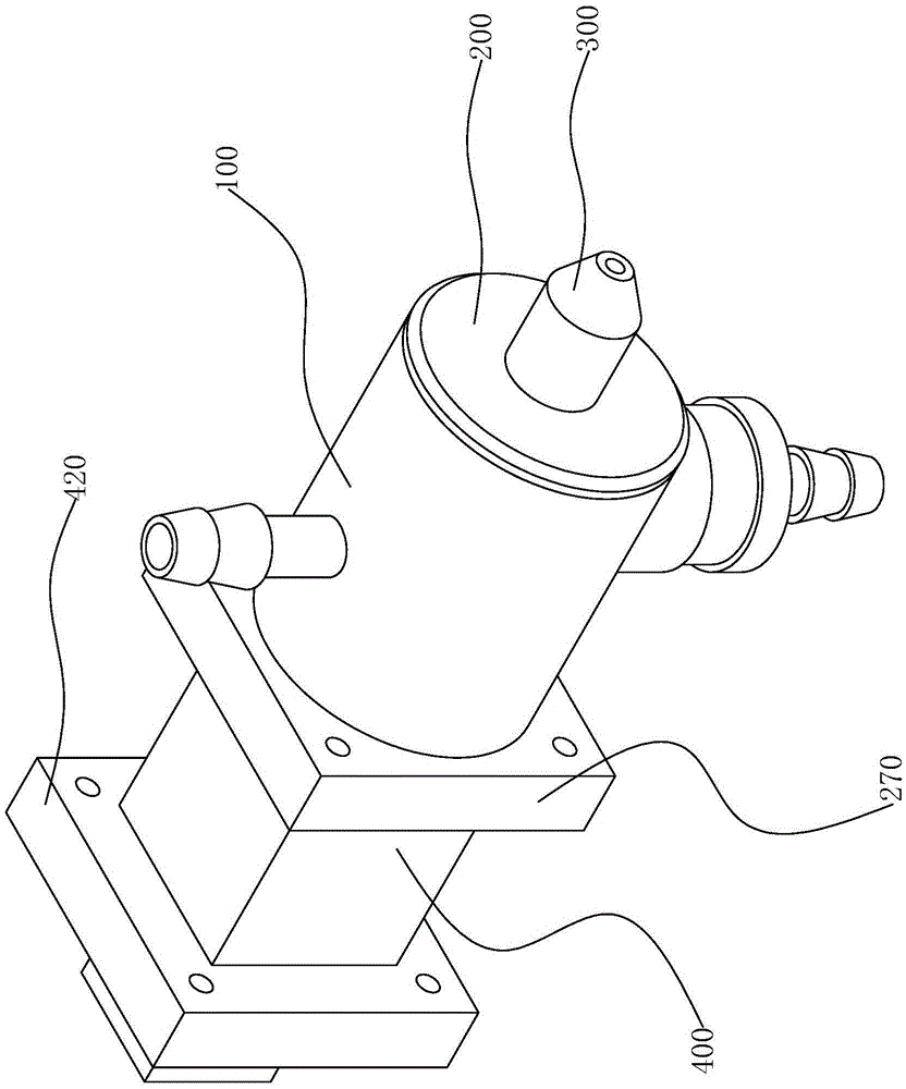
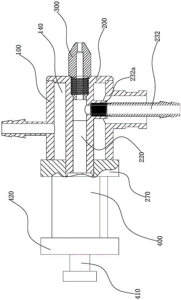
[0040] Such as Figure 1 to Figure 2 As shown, a pneumatically driven thermal insulation wax injection gun of the present invention includes a housing 100 , a gun body 200 , a gun head 300 , and a cylinder 400 .

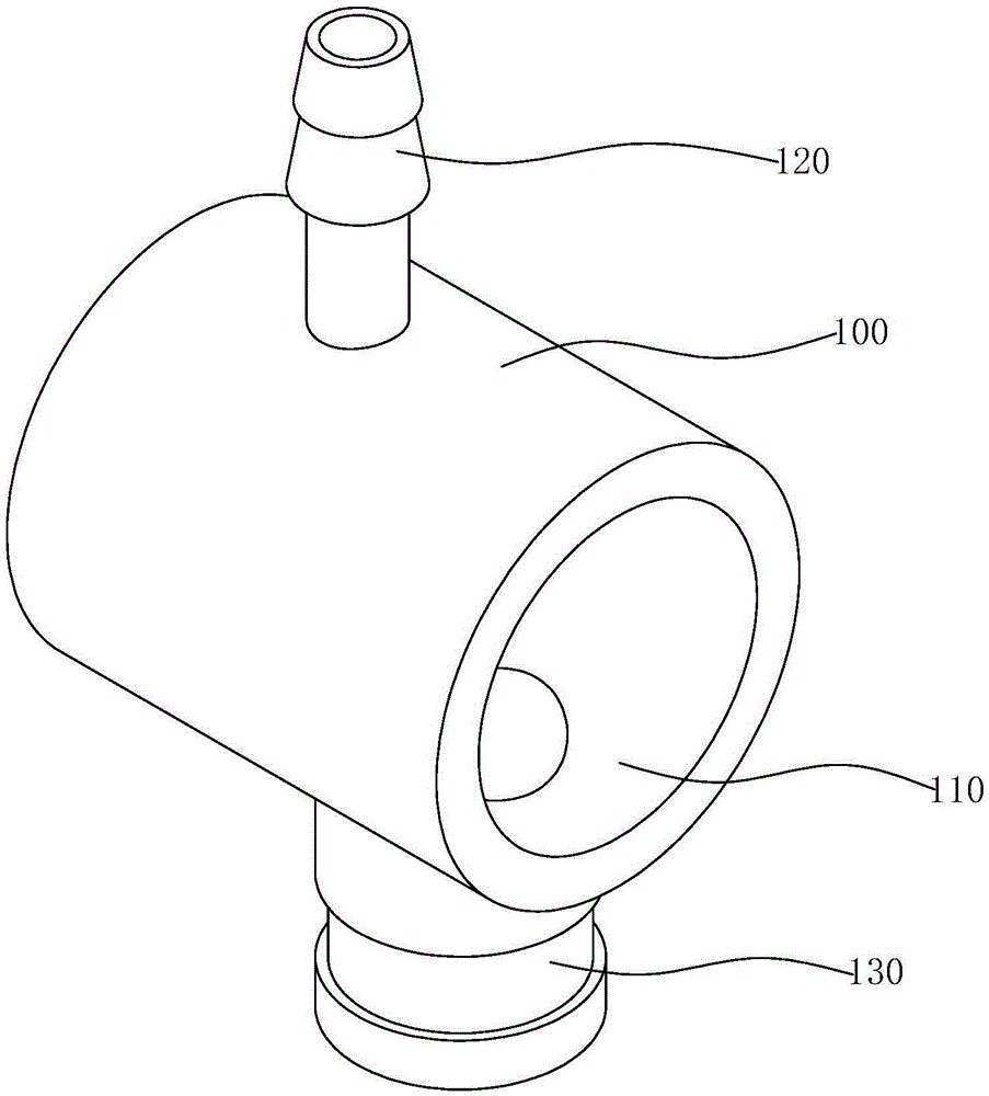
[0041] Such as image 3 , Figure 4 As shown, the casing 100 is long cylindrical and hollow inside to form a cylindrical accommodation chamber 110. The casing 100 is arranged horizontally, and a water inlet pipe 120 is vertically installed on the outer wall of the upper end of the casing 100. The water inlet pipe 120 is connected with the casing. The accommodating cavity 110 of the body 100 communicates, and a water outlet pipe 130 is installed vertically on the outer wall of the lower end of the housing 100. T...


PUM


Abstract

The invention provides an air pressure-driven thermal insulation wax injection gun, which belongs to the technical field of wax processing; it solves the technical problem of poor sealing effect of the existing thermal insulation wax injection gun; an air pressure-driven thermal insulation wax injection gun includes a shell , the gun body and the gun head, the gun body is provided with a through hole, the gun head communicates with the through hole, an annular sealed cavity is formed between the shell and the gun body, and the two sides of the outer wall of the shell are respectively provided with ring-shaped sealed cavities. The water inlet pipe and the water outlet pipe, the gun body is provided with a wax inlet pipe connected to the through hole and the wax inlet pipe is located in the water outlet pipe, the gun body is equipped with a core rod and the core rod is matched with the through hole, and the rear end of the gun body is provided with a cylinder , the piston rod of the cylinder is connected with the core rod, when the core rod moves and covers the wax outlet end of the wax inlet tube, the core rod blocks the wax inlet tube from the through hole; the wax outlet port of the wax inlet tube is sealed by the core rod, The sealing performance inside and outside the through hole is enhanced, so that the wax cannot leak, the wax is fully utilized, and waste and environmental pollution are avoided.

Description

technical field [0001] The invention belongs to the technical field of wax processing, and relates to a thermal insulation wax injection gun, in particular to an air pressure driven thermal insulation wax injection gun. Background technique [0002] Waxes are divided into vegetable waxes, animal waxes, mineral waxes, petroleum waxes and synthetic waxes. With the development of technology, waxes are used more and more widely, whether in life or industry, there are certain application fields. Since the solidification point of wax is relatively high, about between 38 and 90°C, it is prone to solidification during processing. Therefore, in the process of wax processing, it is necessary to ensure that the wax is always in a molten state to ensure the smooth progress of the process. [0003] There are many types of wax injection guns in the prior art, and the wax must be kept at a certain temperature in order to flow in the wax injection gun to prevent it from solidifying. In ord...

Claims


Application Information

Patent Timeline
Patent Type & Authority Patents(China)
IPC IPC(8): B05C5/04
Inventor 王华伟郁自春
Owner 宁波创二代机械科技有限公司
Why Eureka
Try Eureka