Backlight module structure

A backlight module, recessed structure technology, applied in optics, nonlinear optics, instruments, etc., can solve the problems of ineffective use of light, light loss, poor image quality, etc.

Active Publication Date: 2008-07-16
AU OPTRONICS CORP
View PDF5 Cites 0 Cited by
  • Summary
  • Abstract
  • Description
  • Claims
  • Application Information

AI Technical Summary

Problems solved by technology

Therefore, when the light hits the glue inlet point 134 of the light guide plate, because there is no glue frame here to block the light, part of the light is lost from the recess 134, resulting in the inability to use the light effectively, and when the liquid crystal display is in operation, this shadows everywhere
This shadow will cause uneven brightness and poor picture quality of the LCD display

Method used


Image

  • Backlight module structure
  • Backlight module structure
  • Backlight module structure

Examples


Embodiment Construction

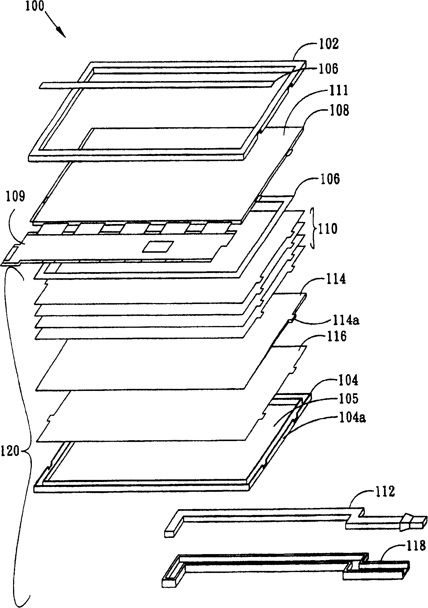
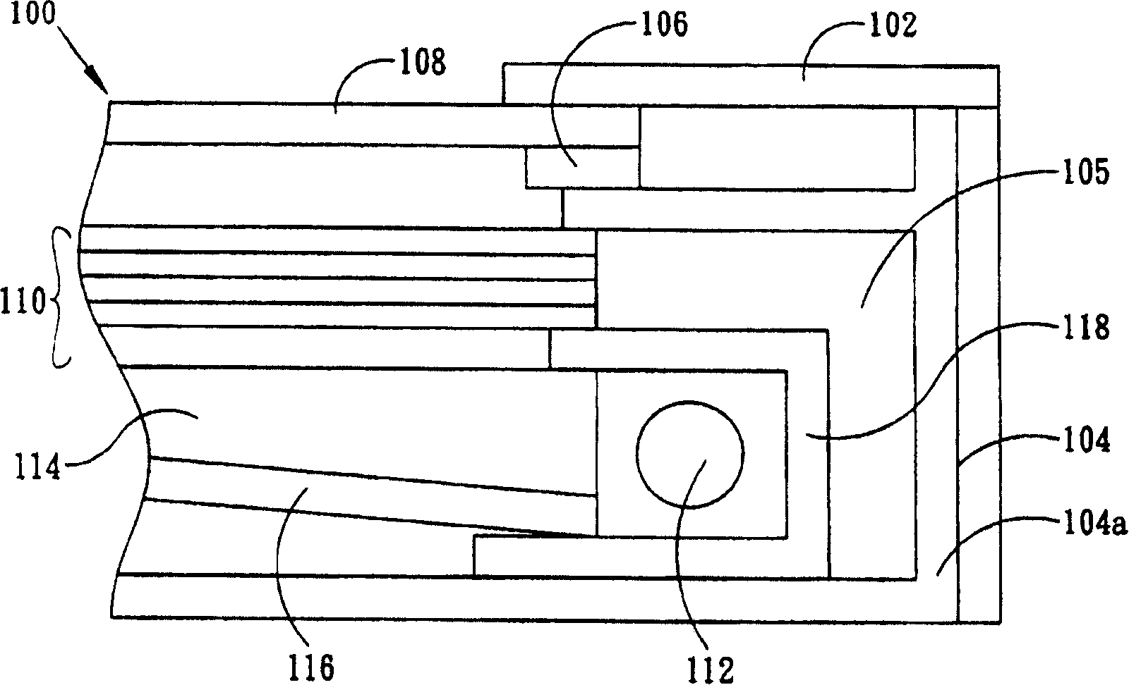
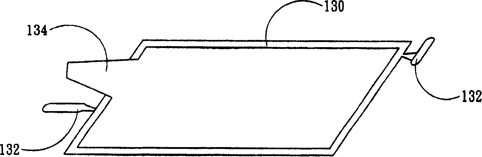
[0014] Some embodiments of the invention are described in detail below. However, the invention can be broadly practiced in other embodiments than this detailed description. That is, the scope of the present invention is not limited by the presented embodiments, but by the present claims. Secondly, when each component or structure in the diagrams of the embodiments of the present invention is described as a single component or structure, it should not be regarded as a limited cognition, that is, when the following description does not particularly emphasize the limitation on the number, the present invention The spirit and scope of application can be extended to structures and methods in which multiple components or structures coexist. Furthermore, in this specification, different parts of each component are not drawn to scale. Certain dimensions have been exaggerated or simplified compared to other relevant dimensions to provide a clearer description and understanding of the...


PUM


Abstract

The invention discloses a negative phototropic module structure. It comprises a shaped body glue frame and light leading plate, a light leading plate glue inlet point on one side of the glue frame, an anti-dazzle film, and a reflecting plate. The negative phototropic module uses the extension of the anti-dazzle film or the reflecting plate to cover the light leading plate glue inlet point so that the light can not be leaked by the light leading plate glue inlet point to generate the dark field.

Description

technical field [0001] The invention relates to a backlight module, in particular to a backlight module which solves the problem of light leakage from an integrally formed plastic frame and a light guide plate. Background technique [0002] With the vigorous development of the optoelectronic industry, liquid crystal display modules (liquid crystal display; LCD) have been widely used in various notebook computers (notebooks), personal digital assistants (personal digital assistants; PDAs) and mobile phones (cell phones), etc. in the electronic device. However, the liquid crystal display is a non-self-illuminating flat panel display, which needs to be illuminated by an external backlight or side light. Therefore, a backlight module is always used as a light source in a liquid crystal display, and the high-brightness and high-uniformity illumination of the backlight module enables the liquid crystal display to efficiently display high-quality pictures. [0003] refer to Figu...

Claims


Application Information

Patent Timeline
Patent Type & Authority Patents(China)
IPC IPC(8): G02F1/1335
Inventor 曾德海宋光涛陈鸿志
Owner AU OPTRONICS CORP
Why Eureka
Try Eureka