

Electromagnetic wave detecting system
A detection system, electromagnetic wave technology, applied in the direction of electromagnetic field characteristics, etc., can solve the problems of cumbersome process, time-consuming and labor-intensive
- Summary
- Abstract
- Description
- Claims
- Application Information
AI Technical Summary
Problems solved by technology
Method used
Image

Examples
no. 1 example
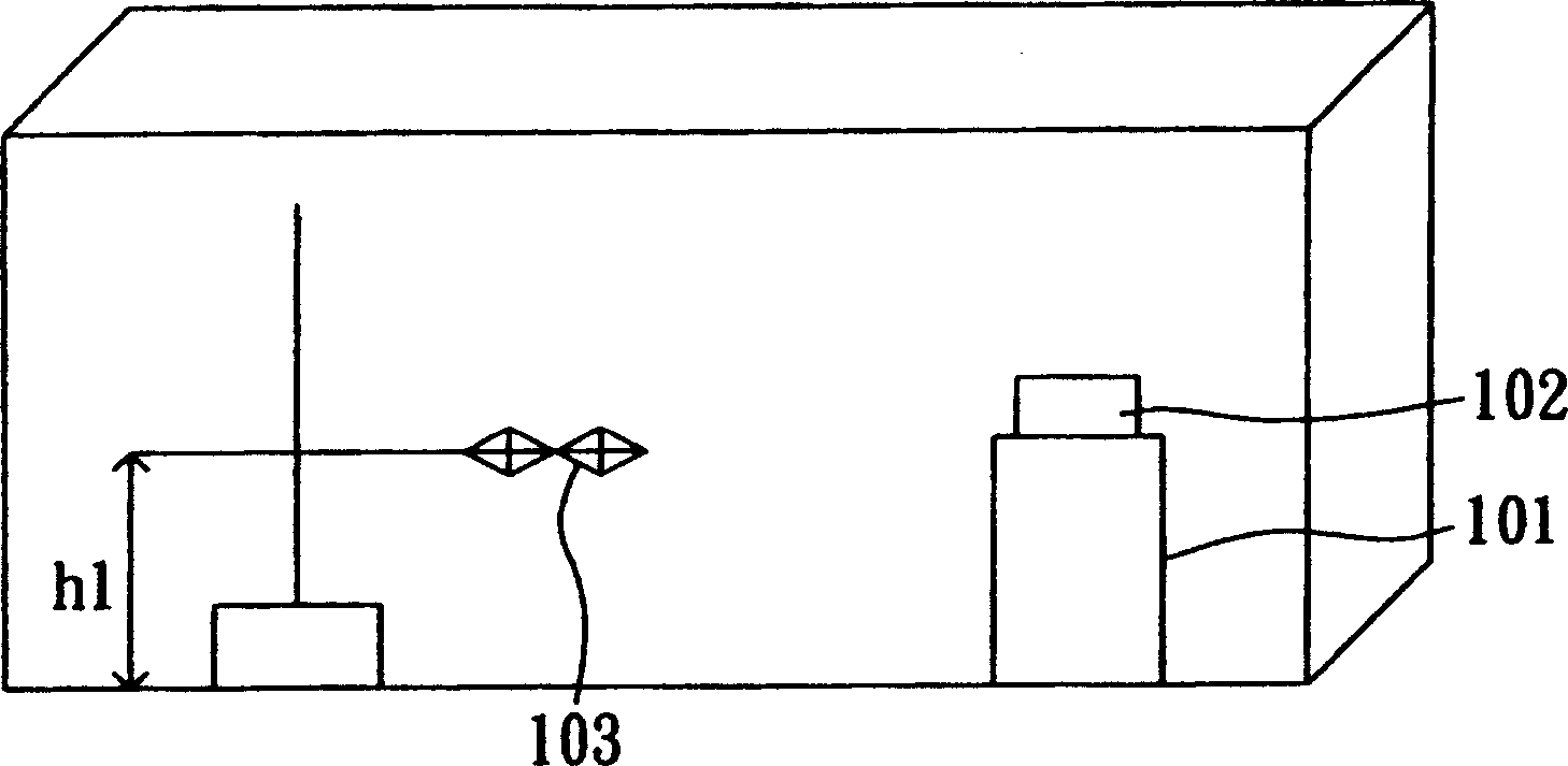
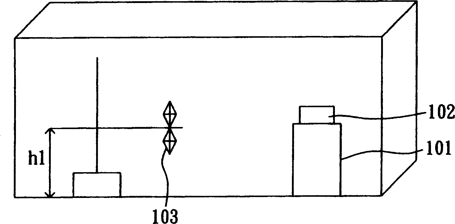
[0021] Please refer to Figure 2A , which is a schematic diagram of the electromagnetic wave detection system of the first embodiment. The electromagnetic wave detection system 290 includes a test bench 201 , a first horizontal antenna 202 , a first vertical antenna 203 and a signal processing unit 204 . Please refer to Figure 2B , which is a schematic diagram of the antenna configuration of the electromagnetic wave detection system of the first embodiment. The test bench 201 is used to place the object under test 210 , the first horizontal antenna 202 is arranged at one place of the anechoic chamber 200 , and the distance between the first horizontal antenna 202 and the object under test 210 is D1. The first vertical antenna 203 is disposed at another place of the anechoic chamber 200 , the distance between the first vertical antenna 203 and the object under test 210 is D2 , and the sizes of D1 and D2 are substantially the same, for example, three meters. Such as Figure...
no. 2 example
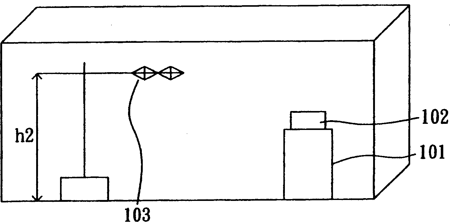
[0025] Please refer to image 3 , which is a schematic diagram of the electromagnetic wave detection system according to the second embodiment of the present invention. The anechoic chamber 200 includes: a test bench 201 , a first horizontal antenna 202 , a second horizontal antenna 302 , a first vertical antenna 203 , and a second vertical antenna 303 . If the anechoic chamber 200 is 7*3*3 meters or 7*4*3 meters in size, the first horizontal antenna 202 and the first vertical antenna 203 are formed by Figure 2C The control unit 230 is adjusted and positioned to a first height h1, such as a height of one meter, and the second horizontal antenna 302 and the second vertical antenna 303 are adjusted and positioned to a second height h2 by the control unit 230, such as a height of two meters. If the anechoic chamber 200 is 9*6*6 meters in size, the first horizontal antenna 202 and the first vertical antenna 203 are adjusted and positioned to the first height h1' by the control u...
no. 3 example
[0027] Please refer to Figure 4 , which is a schematic diagram of an electromagnetic wave detection system according to a third embodiment of the present invention. The anechoic chamber 200 includes: a test bench 201 , a first horizontal antenna 202 , a second horizontal antenna 402 , a first vertical antenna 203 , and a second vertical antenna 403 . If the anechoic chamber 200 has a size of 7*3*3 meters or 7*4*3 meters, the first horizontal antenna 202 and the first vertical antenna 203 are formed as follows: Figure 2CThe control unit 230 is adjusted and positioned to a first height h1, for example, one meter, and the second horizontal antenna 402 and the second vertical antenna 403 are adjusted and positioned by the control unit 230 to a second height h2, for example, two meters. If the anechoic chamber 200 is 9*6*6 meters in size, the first horizontal antenna 202 and the first vertical antenna 203 are adjusted and positioned to the first height h1' by the control unit 23...
PUM
 Abstract
Description
Claims
Application Information