
Plate for a drive for optical storage media

A technology for storage media and drives, which is applied in the field of drive boards, can solve problems such as mechanical damage and movement of scanners, and achieve the effect of reducing costs

Inactive Publication Date: 2006-03-01
THOMSON LICENSING SA
View PDF0 Cites 0 Cited by
  • Summary
  • Abstract
  • Description
  • Claims
  • Application Information

AI Technical Summary

Problems solved by technology

This can cause mechanical damage to the scanner or cause related movement (transmission)

Method used


Image

  • Plate for a drive for optical storage media
  • Plate for a drive for optical storage media
  • Plate for a drive for optical storage media

Examples


Embodiment Construction

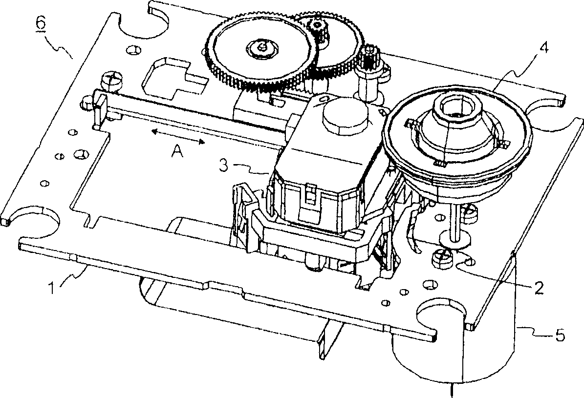
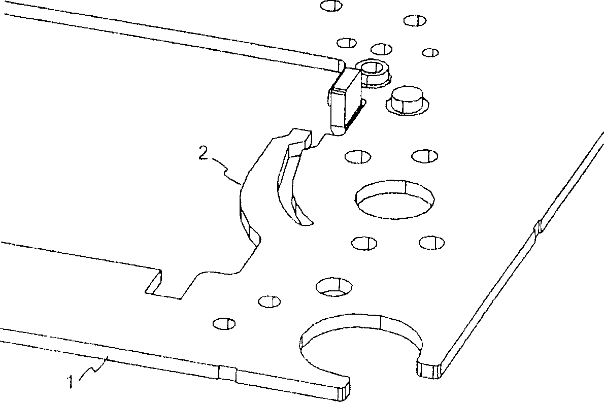
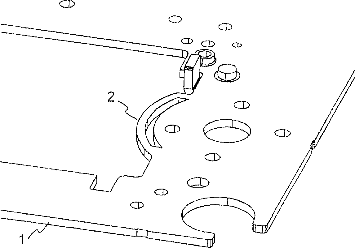
[0019] figure 1 A board 1 according to the invention is shown within a drive 6 for an optical storage medium. In the drop test, the optical scanner 3 moves at a high speed relative to the spring-like elastic portion 2 on the board. The elastic part 1 itself is formed from a plate. Through the elastic deformation of the plate 1 in the region of the spring-like part 2 , a damping effect on the optical scanner 3 moving at high speed is achieved. The drop test requirements are met without adding additional parts. Flexible materials such as rubber or plastic are not required.

[0020] The elastic part 2 causes the optical scanner 3 to spring back slightly. However, this has no disturbing effect, since the acceleration caused by the spring-back process is smaller than in the direction of the spring arm. According to an advantageous development, the spring arm moves elastically by 0.3 mm. After the first drop test, 0.2 mm of elastic movement remained, since about 0.1 mm of the...


PUM


Abstract

In drop tests, the optical scanner (3) of a drive (6) of this type falls at high speed against a mechanical stop (2). Said stop is located on a plate (1) of the drive (6). The fall can cause mechanical damage to the optical scanner (3) or an associated drive. According to the invention, part (2) of the plate (1) is configured in a sprung manner and acts as an elastic stop for the optical scanner (3).

Description

technical field [0001] The present invention relates to a board for a drive of an optical storage medium and to a device having a board such as this for reading from and / or writing to an optical storage medium enter. Background technique [0002] A device for reading from and / or writing to an optical storage medium utilizes an optical scanner for reading information from and storing information on data tracks located on the optical storage medium, wherein the optical storage medium The medium is such as a compact disc (CD) or a digital versatile disc (DVD). For this purpose, the optical scanner is movable relative to the data track, and the movement of the optical scanner is generally at right angles to the track. [0003] Figure 8 A drive 6 of a device such as this for reading from and / or writing to an optical storage medium is shown. The drive 6 has a plate 1 on which a turntable 4 is mounted, which is driven by a motor 5 . The plate 1 has a cutout in which the optica...

Claims


Application Information

Patent Timeline
IPC IPC(8): G11B7/085
CPCG11B7/08582
Inventor 冈特·泰伯赖纳·巴斯罗尔夫·杜珀
Owner THOMSON LICENSING SA
Learn More