Method and device for electrostatic coating

A technology for electrostatic spraying and spraying materials, applied in the direction of liquid supply device, etc., can solve the problems of increasing the amount of conductive spraying materials, uneconomical and enlarged electrostatic spraying equipment, etc., and achieve simple treatment and installation, economical and effective electrostatic spraying treatment Effect

Active Publication Date: 2006-04-19
HONDA MOTOR CO LTD
View PDF1 Cites 5 Cited by
  • Summary
  • Abstract
  • Description
  • Claims
  • Application Information

AI Technical Summary

Problems solved by technology

[0016] Therefore, in each cleaning process, the unused conductive spraying material in the insulating pipe 2b is unnecessarily discharged, resulting in an increase in the amount of the conductive spraying material
In particular, if the

Method used


Image

  • Method and device for electrostatic coating
  • Method and device for electrostatic coating
  • Method and device for electrostatic coating

Examples


Embodiment Construction

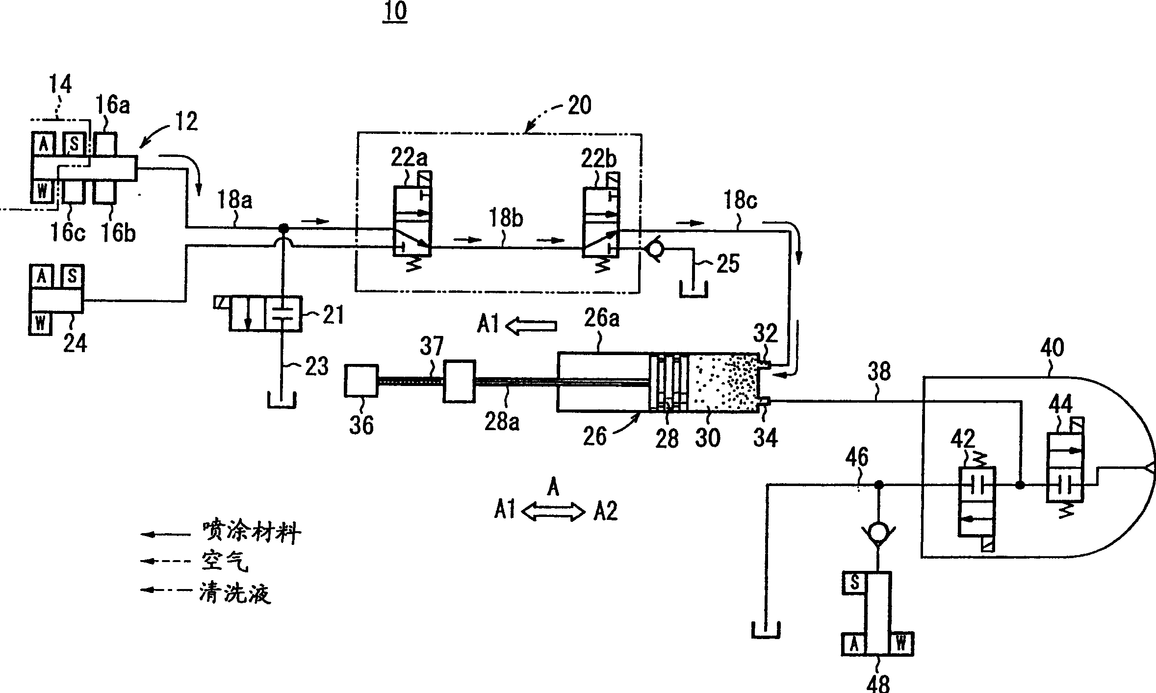
[0039] FIG. 1 is a schematic diagram of an electrostatic spraying apparatus 10 for performing an electrostatic spraying method according to the present invention.

[0040] The electrostatic spraying apparatus 10 includes a grounded color changer valve mechanism 12 with a first purge valve 14 for controlling the supply of drying air (A), water (W), cleaning solution (S) etc. A plurality of spray material valves 16a, 16b, 16c for conductive spray material. The choke valve mechanism 20 is connected to the color changer valve mechanism 12 through the supply passage 18 a, and the first discharge passage 23 is connected to the supply passage 18 a through the first damper valve 21 .

[0041] The choke valve mechanism 20 has an electrically insulating tube (supply passage) 18b made of resin and a pair of directional control valves 22a, 22b connected to respective opposite ends of the electrically insulating tube 18b. The directional control valve 22a on the inlet side selects one of ...


PUM


Abstract

An intermediate storage vessel (26) has a cylinder container (26a), a piston (28) provided in the cylinder container (26a) so as to be slidable in a reciprocating manner, and an inpour hole portion (32) and a discharge hole portion (34) that are opened in a cylinder chamber (30) where the piston (28) slides. The inpour hole portion (32) is provided above the discharge hole portion (34). An insulation cover (70) is provided so as to cover the intermediate storage vessel (26) and an insulation mechanism (20), and the cover is removable from the insulation mechanism (20) side.

Description

technical field [0001] The present invention relates to a method and apparatus for carrying out electrostatic spraying by temporarily supplying a spraying material from a supply source to a spraying material container, thereafter electrically insulating the supply source and the spraying material container from each other and supplying the spraying material to a spray gun to spray the material . Background technique [0002] For example, voltage blocking is known as a process for applying a high voltage to a conductive spray material to electrostatically spray an object to be painted, such as a motor vehicle body. According to this process, conductive spraying material is temporarily introduced into an intermediate storage container (intermediate storage mechanism) insulated from ground potential, after which the supply path connecting the intermediate storage container and the supply source of the spraying material to each other is cleaned and dried, to form a voltage barr...

Claims


Application Information

Patent Timeline
IPC IPC(8): B05B5/16
Inventor 武部诚司国保敏幸植木孝幸庄司正明熊野义之
Owner HONDA MOTOR CO LTD
Why Eureka
Try Eureka