Tensioner

a technology of tensioner and cylinder, which is applied in the direction of belt/chain/gearing, mechanical equipment, belts, etc., can solve the problems of severe consequences, achieve the effect of preventing an impermissible pivot range of the working cylinder, facilitating the handling and installation of the tensioner, and preventing extreme excursions

Inactive Publication Date: 2005-08-23
INA SCHAEFFLER KG
View PDF13 Cites 44 Cited by
  • Summary
  • Abstract
  • Description
  • Claims
  • Application Information

AI Technical Summary

Benefits of technology

[0007]According to one aspect of the present invention, a tensioner includes a locking mechanism which has a fixed position with respect to the faceplate after the initial installation of the working eccentric member. This approach simplifies the handling and installation of the tensioner and the traction member, since the working eccentric member assumes hereby a position that corresponds to the un-tensioned traction member. The tensioner according to the invention further includes a catch which limits the pivot range or adjustment angle of the working cylinder relative to the faceplate. The catch which becomes active after the release of the locking device affects the degree of freedom, preventing an impermissible pivot range of the working cylinder. The catch is dimensioned so that the working eccentric member can assume all positions under normal operation of the traction member, while simultaneously preventing extreme excursions of the working eccentric member. A traction member formed as a toothed belt is thereby effectively prevented from skipping a tooth, which can result in severe consequences, for example, changing control times of the gas exchange valves of an internal combustion engine.
[0008]The tensioner according to the invention includes a faceplate, which is stationarily affixed on a machine part, primarily a housing of the internal combustion engine, when the tensioner is installed. This prevents a change in position or a subsequent rotation of the entire tensioner, when the attachment device is screwed in. At the same time, this design provides a precise and always reproducible installation position of the tensioner relative to the machine part. The tensioner according to the invention is therefore suited for automatic assembly, because the articulation points and support points of the tensioner are precisely defined. The invention advantageously guarantees that the traction member is pre-tensioned in substantial agreement with a predetermined tension of the traction member, thereby increasing the reliability of the entire traction drive. The simple construction of the tensioner according to the invention in conjunction with a simplified assembly process provides significant cost advantages. In addition, only minor changes to the tensioner according to the invention are required to mate with the contact and / or support surface of the machine part, in particular the housing of an internal combustion engine, produced in series.
[0009]According to another feature of the present invention, the catch may effectively be implemented to define the adjustment range of the working eccentric member, by a spring-biased pin, a retainer button or pushbutton, which interlocks with an oblong hole of the corresponding additional component, when their position overlaps. The spring-biased pin is constructed so as to automatically and form-fittingly engage the oblong hole after the locking device is released. The retainer button, pin or pushbutton is designed so as not to influence the operating range or the operation of the working eccentric member, and is hence guided in the oblong hole with play. The catch is hence only provided for preventing extreme positions of the working eccentric member which can, as described above, have an adverse effect on the operation of the traction member and the equipment connected thereto.

Problems solved by technology

A traction member formed as a toothed belt is thereby effectively prevented from skipping a tooth, which can result in severe consequences, for example, changing control times of the gas exchange valves of an internal combustion engine.

Method used


Image

  • Tensioner
  • Tensioner
  • Tensioner

Examples


Embodiment Construction

[0026]Throughout all the Figures, same or corresponding elements are generally indicated by same reference numerals. Embodiments and modifications thereof as described in the figures are to be understood only as exemplary and in no way as limiting the scope of the invention.

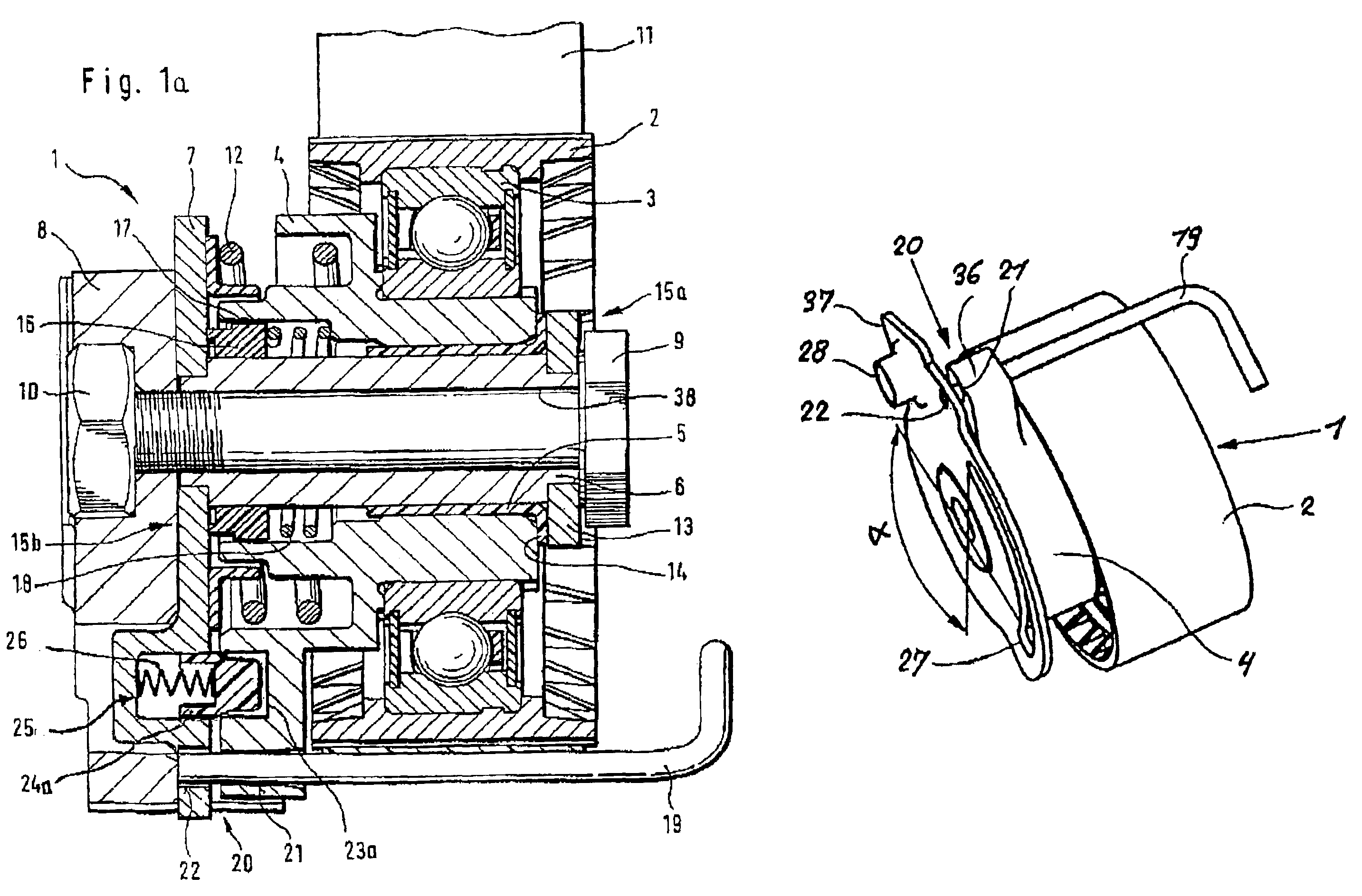
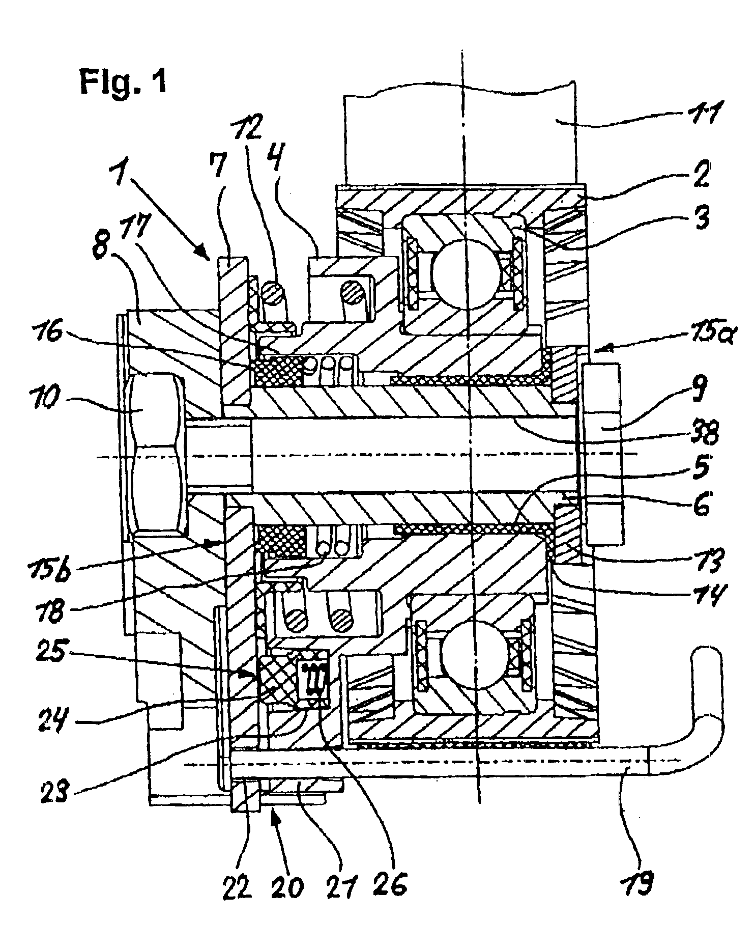
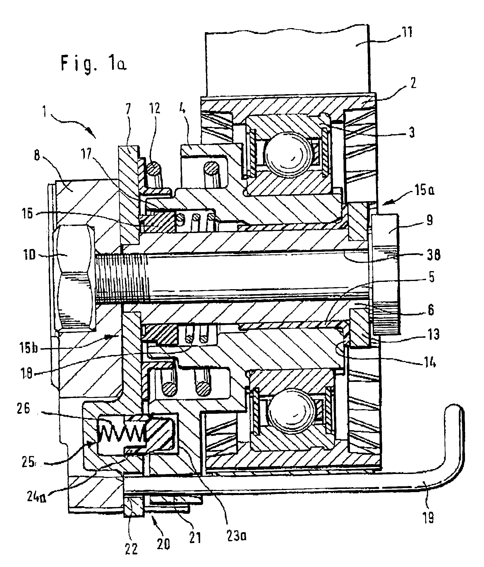
[0027]Turning now to the drawing, and in particular to FIG. 1, there is shown a longitudinal section of a tensioner according to the present invention, generally designed by reference numeral 1 includes a tensioning roller 2 supported by a roller bearing 3 disposed on the outside of a working eccentric member 4. The working eccentric member 4 is supported for rotation on a support body 6 by a sliding bearing 5, wherein the support body 6 is affixed to a faceplate 7 and forms a subassembly. The faceplate 7 can be attached to a machine part 8 and prevents the entire tensioner 1 from rotating relative to the machine part 8, which is preferably a housing of an internal combustion engine (not shown in FIG. 1). The ten...


PUM


Abstract

A tensioner for a traction member includes a faceplate that is stationarily secured to a machine part, with a working eccentric member rotatably supported on the faceplate for limited rotation against a spring force. After pre-installation of the tensioner, a locking device fixes the position of the working eccentric member relative to the faceplate. In one installation position, a catch limits the pivot range of the working eccentric member.

Description

CROSS-REFERENCES TO RELATED APPLICATIONS[0001]This application claims the benefit of prior filed provisional application, Application Ser. No. 60 / 303,326, filed Jul. 5, 2001, pursuant to 35 U.S.C. 119(e), the subject matter of which is incorporated herein by reference.BACKGROUND OF THE INVENTION[0002]The present invention relates to a tensioner for traction members, in particular belts, for a traction drive.[0003]Tensioners of this type are used for a traction drive for power units or control belts of an internal combustion engines. The tensioner has a faceplate that is affixed stationarily to a machine part, for example the housing of an internal combustion engine, to which a support body is affixed in fixed rotative engagement. The support body is adapted to receive a working eccentric member that can be rotated against a spring force. A tensioning roller is associated with the working eccentric member and supported on the traction member.[0004]U.S. Pat. No. 4,832,665 describes a ...

Claims


Application Information

Patent Timeline
Patent Type & Authority Patents(United States)
IPC IPC(8): F16H7/12F16H7/08
CPCF16H7/1218F16H2007/081F16H2007/0846F16H2007/0878
Inventor KAISER, JORGGRAF, HERBERT
Owner INA SCHAEFFLER KG
Why Eureka
Try Eureka