Compressors muffler

A muffler and compressor technology, applied in the field of compressors, can solve the problems of cost increase, large impact noise, etc., and achieve the effect of cost reduction and avoid impact noise

Inactive Publication Date: 2006-04-26
LG ELECTRONICS (TIANJIN) APPLIANCES CO LTD
View PDF0 Cites 11 Cited by
  • Summary
  • Abstract
  • Description
  • Claims
  • Application Information

AI Technical Summary

Problems solved by technology

In this case, the refrigerant discharged from the discharge hole 13 will directly impact the rotor 22 above the muffler 38, thus generating a relatively large impact noise.
In addition, since this muffler 38 reduces noise by increasing the inner plate 12, the cost of the product will be increased.

Method used


Image

  • Compressors muffler
  • Compressors muffler
  • Compressors muffler

Examples


Embodiment Construction

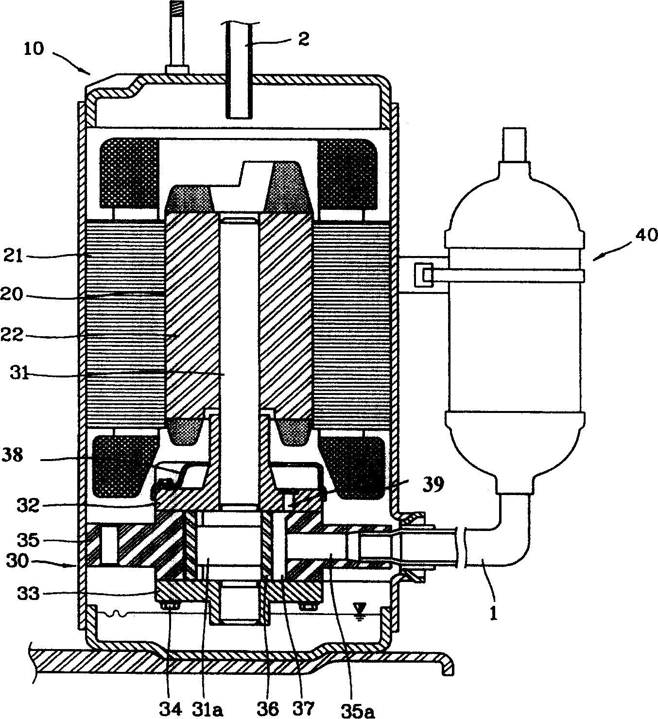
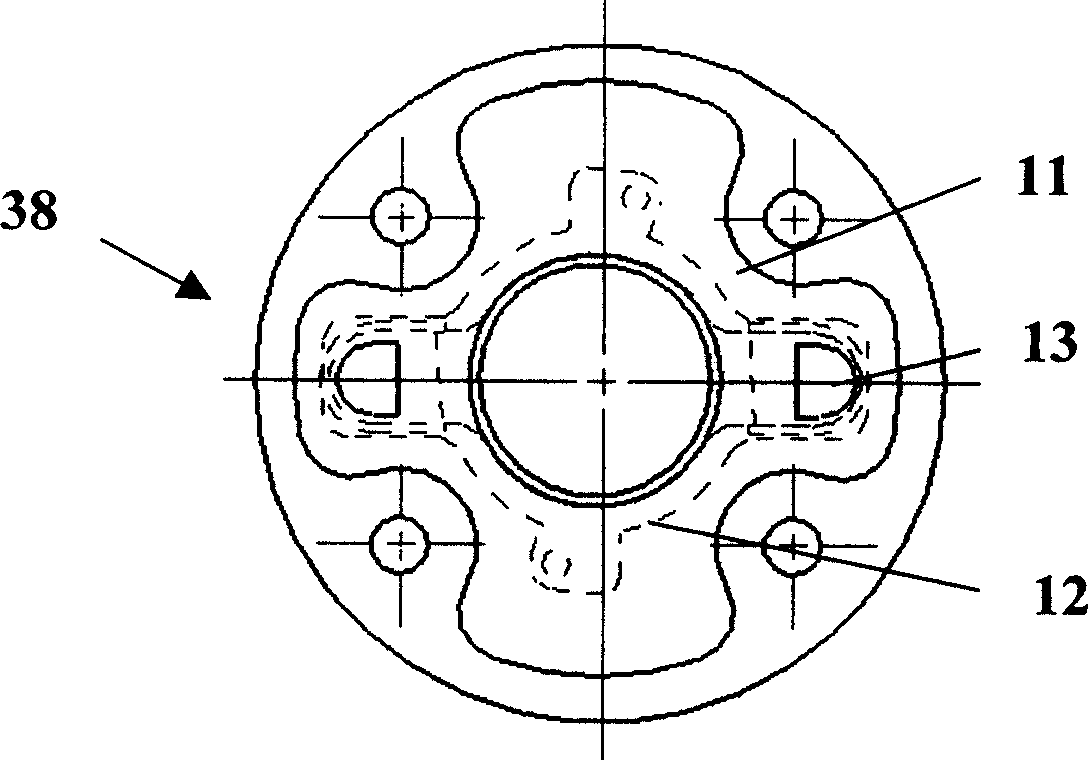
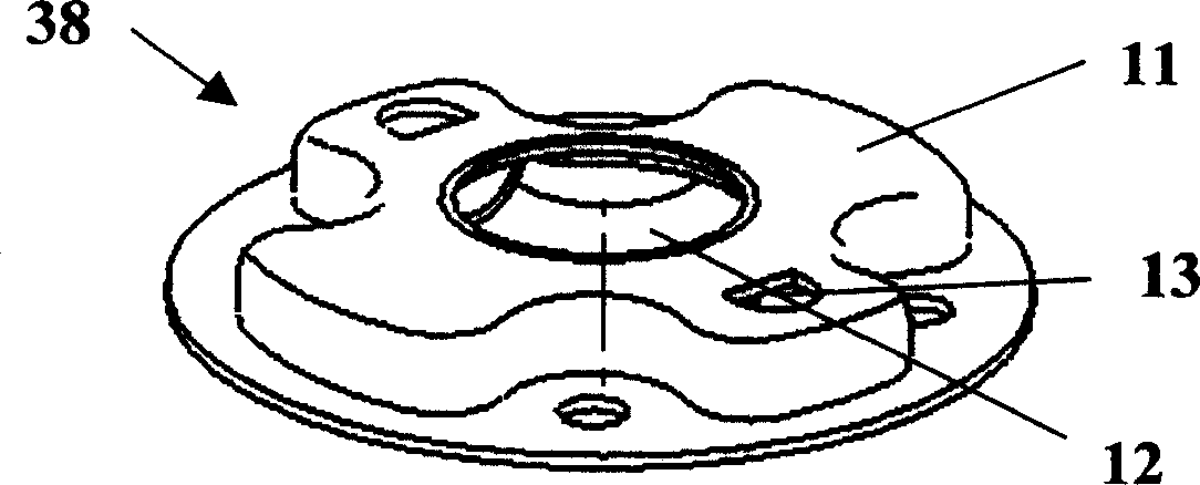
[0011] Such as Figure 4 As shown, the compressor muffler 50 provided by the present invention consists of a cross-shaped protrusion 52 with a crankshaft through hole 51 formed in the center and a chassis 53 formed by extending outward from the lower end of the protrusion 52 in a horizontal direction and having a circular outer periphery. Composition; The two ends of the cross-shaped protrusion 52 are respectively provided with a discharge hole 54 penetrating in the radial direction and penetrating through the chassis 53 . When the compressor is running, the compression mechanical part 30 can compress the low-temperature and low-pressure gaseous refrigerant sucked from the liquid storage tank 40 through the suction pipe 1 into a high-temperature and high-pressure gaseous refrigerant, and then discharge the compressed refrigerant from the discharge port 39 on the upper bearing 32 into the muffler 38. The refrigerant entering the interior of the muffler 38 will flow in the hori...


PUM


Abstract

The invention discloses a compressor silencer, which is characterized by the following: forming a cross-shaped projecting part of crank through hole in the central part; extending outsides along the horizontal direction of projecting part to form a circular chassis structure; setting outlet hole along radial direction and through the chassis on two sides of cross-shaped projection part separately. The silencer is set on two lateral ends without setting inner plate, which avoids the noise of the rotor impaction directly.

Description

technical field [0001] The invention relates to a compressor, in particular to a compressor muffler capable of reducing impact noise and cost. Background technique [0002] Generally speaking, the rotary compressor does not rely on centrifugal force, but compresses the refrigerant through the rotation of the roller ring in the cylinder, that is, relies on the eccentric roller ring installed at the lower part of the crankshaft to rotate and revolve along the inner peripheral surface of the cylinder to compress the refrigerant. Inhale and compress. figure 1 It is a forward structural sectional view of a rotary compressor in the prior art. figure 2 for figure 1 Cross-sectional view of the longitudinal structure of the middle compressor muffler. image 3 It is a structural perspective view of a compressor muffler in the prior art. Such as figure 1 As shown, the interior of this prior art rotary compressor is formed with a closed space, which includes: a closed housing 10 p...

Claims


Application Information

Patent Timeline
Patent Type & Authority Applications(China)
IPC IPC(8): F04C29/06
Inventor 朱相民
Owner LG ELECTRONICS (TIANJIN) APPLIANCES CO LTD
Why Eureka
Try Eureka