Moving in and out device for food supporting rack

A technology for supporting racks and food, applied in the direction of stove/stove brackets/shelves, etc., can solve the problems of prolonged heating time, troublesome operation, and unsafety of food, and achieve the effects of saving heating time, improving heating efficiency, and ensuring safe use

Active Publication Date: 2006-05-03
MIDEA GRP CO LTD
View PDF0 Cites 3 Cited by
  • Summary
  • Abstract
  • Description
  • Claims
  • Application Information

AI Technical Summary

Problems solved by technology

[0002] In existing food cooking stoves such as microwave ovens and ovens, the food support frame used for placing food is sent to the heating position in the oven cavity and the operation of the support frame being taken out of the oven cavity is done manually by the user. Not only is the operation troublesome, time-consuming and labor-intensive, but also the temperature of the support frame is high when the food is heated in the oven cavity. It is extremely unsafe for the user to manually take the support frame out of the oven cavity. burns, it is difficult to ensure the safety of users; in addition, manual operation is also difficult to ensure that the food support frame is accurately sent to the best heating position in the oven cavity, so as to affect the heating efficiency of the stove, prolong the heating time of food, and also affect the cooking effect of the food

Method used


Image

  • Moving in and out device for food supporting rack
  • Moving in and out device for food supporting rack
  • Moving in and out device for food supporting rack

Examples


Embodiment

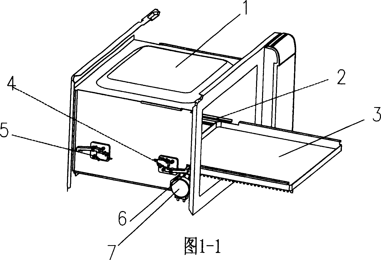
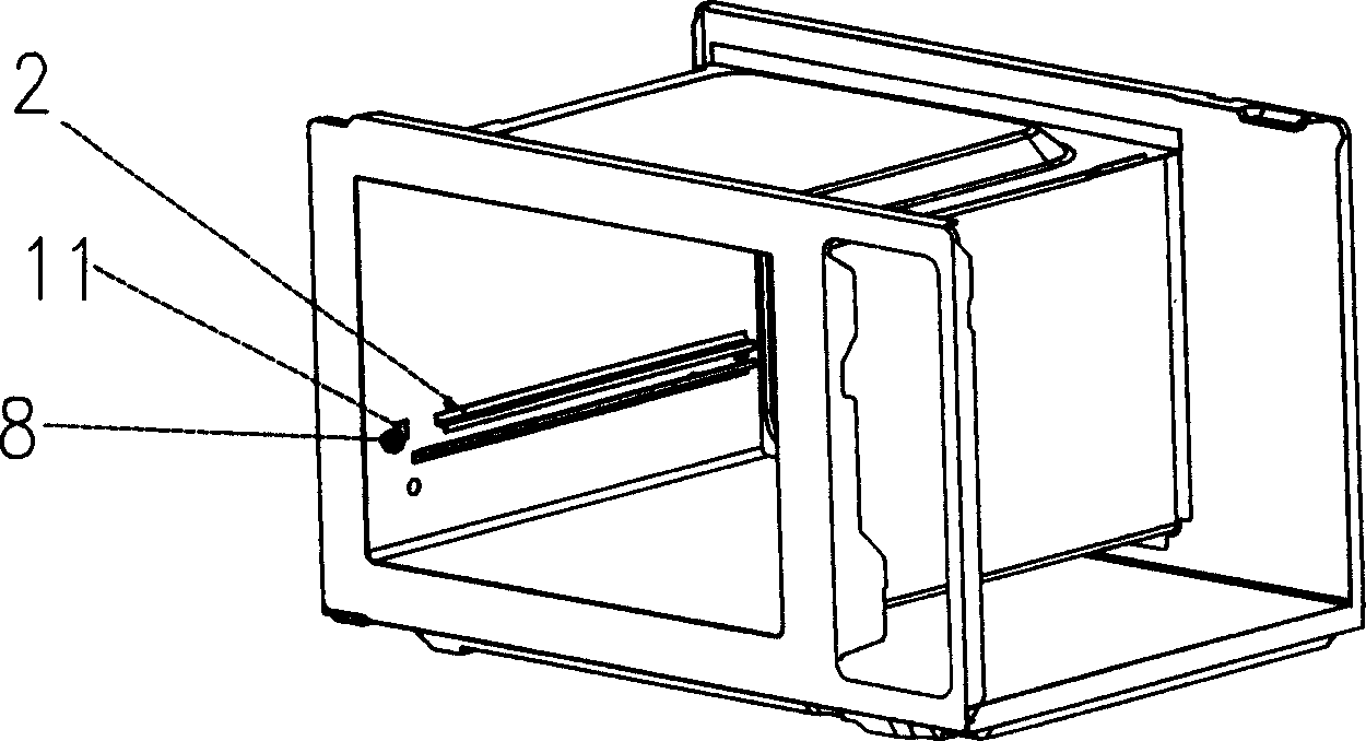
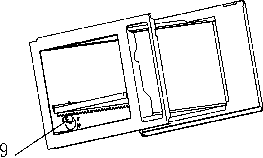
[0029] The schematic diagram of the structure of the present invention is shown in Figure 1, including the raceway 2 fixed on both sides of the oven cavity 1, the food support frame 3, the normally closed switch device 5 for setting the heating position, and the setting for moving out the position. Normally closed switchgear 4, rotating motor support 6, rotating motor 7, gear 9, rack 10, wherein two raceways 2 are fixed on the two side plates in the furnace cavity, and the food support frame 3 is placed on both sides for rolling On Road 2, the normally closed switch device 5 for setting the heating position and the normally closed switch device 4 for setting the moving position are respectively fixed at both ends of the side plate outside the furnace cavity, and the rotating motor bracket 6 is fixed on the side plate outside the cavity On, rotary motor 7 is fixed on rotary motor support 6, and gear 9 is fixed on the output shaft of rotary motor 7, and tooth bar 10 meshes with g...


PUM


Abstract

The invention discloses a to-and-fro device of food support rack, which comprises the following parts: ball track, food support rack, normal-close switch device at the heating position, normal-close switch device at the shift out position, rotary motor rack, rotary motor, gear and rack bar, wherein two ball tracks are fixed on two sides of stove cavity; the food support rack is set on two sides of ball track; the normal-close switch device at the heating position and normal-close switch device at the shift out position are fixed on two side plate ends out of stove cavity separately; the rotary motor rack is fixed on the side plate out of cavity to support the rotary motor; the gear is fixed on the output shaft of rotary motor; the rack bar engages the gear, which is fixed on the food support rack. The invention avoids the scalding accident, which can place the food support rack to the optimum heating position.

Description

1. Technical field: [0001] The invention relates to a device for entering and exiting a food support frame used in food cooking stoves such as microwave ovens and ovens, and belongs to the modification technology of the food support frame entering and exiting device. 2. Background technology: [0002] In existing food cooking stoves such as microwave ovens and ovens, the food support frame used for placing food is sent to the heating position in the oven cavity and the operation of the support frame being taken out of the oven cavity is done manually by the user. Not only is the operation cumbersome, time-consuming and labor-intensive, but also the temperature of the support frame is high when the food is heated in the oven cavity. It is extremely unsafe for the user to manually take the support frame out of the oven cavity. burns, it is difficult to ensure the safety of users; in addition, manual operation is also difficult to ensure that the food support frame is accuratel...

Claims


Application Information

Patent Timeline
Patent Type & Authority Applications(China)
IPC IPC(8): F24C15/16
Inventor 余悦泳邱晓锋
Owner MIDEA GRP CO LTD
Why Eureka
Try Eureka