In-out control device for food supporting rack

A technology of a control device and a supporting frame, which is applied in the directions of household heating, lighting and heating equipment, household heating, etc., can solve the problems of prolonged food heating time, troublesome operation, insecurity, etc., so as to save heating time and improve heating efficiency. , the effect of avoiding scalding accidents

Inactive Publication Date: 2008-04-16
MIDEA GRP CO LTD
View PDF4 Cites 0 Cited by
  • Summary
  • Abstract
  • Description
  • Claims
  • Application Information

AI Technical Summary

Problems solved by technology

[0002] In existing food cooking stoves such as microwave ovens and ovens, the food support frame used for placing food is sent to the heating position in the oven cavity and the operation of the support frame being taken out of the oven cavity is done manually by the user. Not only is the operation troublesome, time-consuming and labor-intensive, but also the temperature of the support frame is high when the food is heated in the oven cavity. It is extremely unsafe for the user to manually take the support frame out of the oven cavity. burns, it is difficult to ensure the safety of users; in addition, manual operation is also difficult to ensure that the food support frame is accurately sent to the best heating position in the oven cavity, so as to affect the heating efficiency of the stove, prolong the heating time of food, and also affect the cooking effect of the food

Method used


Image

  • In-out control device for food supporting rack

Examples


Embodiment

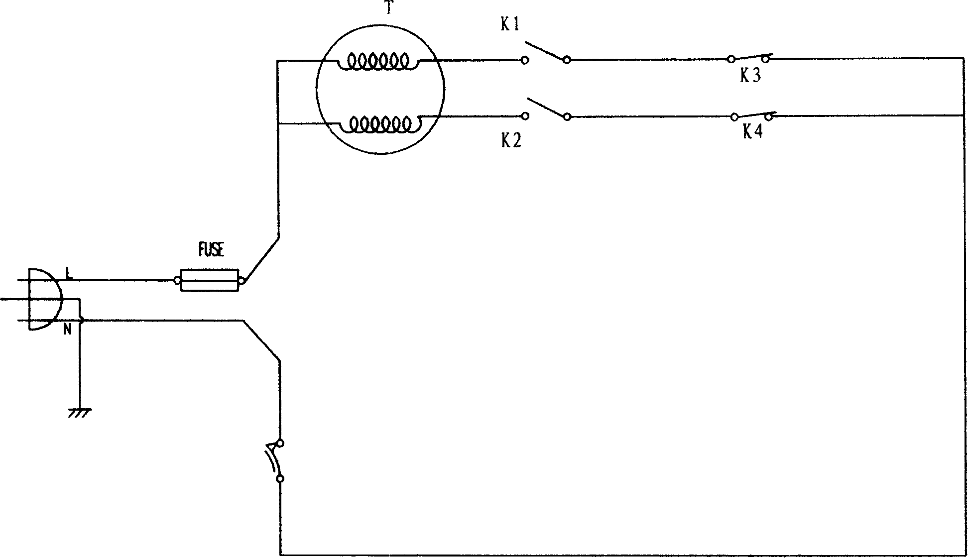
[0011] The schematic circuit diagram of the present invention is as figure 1 As shown, it includes a first manual switch K1, a second manual switch K2, a two-way controllable motor T, a first normally closed switch K3 for setting the heating position, and a second normally closed switch K4 for setting the moving position, wherein The first normally closed switch K3 is connected in series with the first manual switch K1 and the bidirectional controllable motor T, the second normally closed switch K4 is connected in series with the second manual switch K2 and the bidirectional controllable motor T, and the two series circuits are connected in parallel. One end of the parallel circuit is connected to the live line L of the power supply, and the other end of the parallel circuit is connected to the neutral line N of the power supply. In this embodiment, the second normally closed switch K4 and the first normally closed switch K3 are normally closed micro switches. The first manua...


PUM


Abstract

This invention relates to a device for controlling the food bearer frame in and out the furnace chamber of the food cooking furnace such as microwave stove and oven, which comprises manual switch (k1), manual switch (k2), bilateral controlling motor (T), normal close switch (k3) used for setting heating place, normal close switch (k4) used for setting explantation place, wherein the normal close switch (k3), the manual switch (k1) and the bilateral controlling motor (T) are cascade, the normal close switch (k4), the manual switch (k2) and the bilateral controlling motor (T) are cascade, and the two cascading circuits are in parallel; one end of the parallel circuit connects the live line L of the power source, while the other end connects the zero line N of the power source.

Description

1. Technical field: [0001] The invention relates to a control device used in food cooking stoves such as microwave ovens and ovens for controlling the entry and exit of a food support frame into and out of a furnace cavity, and belongs to the transformation technology of the food support frame entry and exit control device. 2. Background technology: [0002] In existing food cooking stoves such as microwave ovens and ovens, the food support frame used for placing food is sent to the heating position in the oven cavity and the operation of the support frame being taken out of the oven cavity is done manually by the user. Not only is the operation cumbersome, time-consuming and labor-intensive, but also the temperature of the support frame is high when the food is heated in the oven cavity. It is extremely unsafe for the user to manually take the support frame out of the oven cavity. burns, it is difficult to ensure the safety of users; in addition, manual operation is also di...

Claims


Application Information

Patent Timeline
Patent Type & Authority Patents(China)
IPC IPC(8): F24C15/00
Inventor 邱小锋余悦泳
Owner MIDEA GRP CO LTD
Why Eureka
Try Eureka