Vacuum cleaner grip

A technology for vacuum cleaners and handles, which is applied in the field of vacuum cleaners and can solve problems such as power cord body 20 detachment

Inactive Publication Date: 2006-05-10
LG ELECTRONICS (TIANJIN) APPLIANCES CO LTD
View PDF0 Cites 1 Cited by
  • Summary
  • Abstract
  • Description
  • Claims
  • Application Information

AI Technical Summary

Problems solved by technology

However, such a power cord 21' has a certain length, so when the user uses the vacuum cleaner at a place far away from the power socket, the power cord 21' is easily detached from the body 20.

Method used


Image

  • Vacuum cleaner grip
  • Vacuum cleaner grip
  • Vacuum cleaner grip

Examples


Embodiment Construction

[0034] The embodiments of the vacuum cleaner involved in the present invention will be described in detail below with reference to the accompanying drawings.

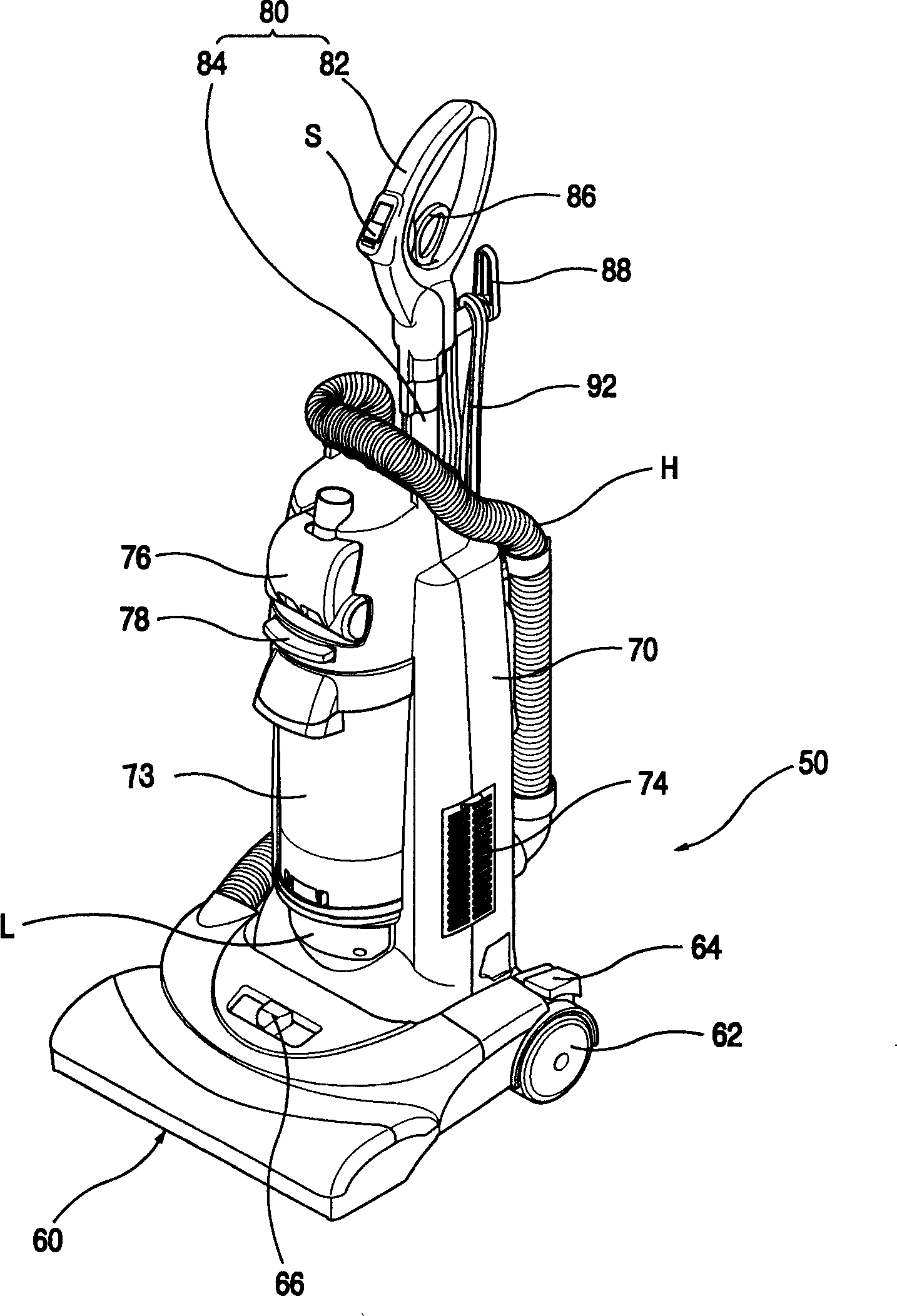
[0035] figure 2 It is a perspective view of an upright vacuum cleaner using the handle of the present invention.

[0036] Such as figure 2 As shown, the upright vacuum cleaner 50 includes a suction head 60 , a body 70 and a handle 80 . Wherein, the suction head 60 inhales air containing foreign matter while moving on the ground; a device for generating a suction force for sucking air containing foreign matter through the suction head 60 is arranged in the body; the handle 80 is equipped on the upper part of the body 70, and the user can Easy to hold.

[0037] The suction head 60 has a structure that moves in a state close to the ground and sucks air through a suction port (not shown) on the bottom surface. That is, the suction port of the main passage of external air is formed on the bottom surface of the suction ...


PUM


Abstract

The invention relates to a handle of vacuum dust-collector with a channel for fixing power cord and a fixing rib, which comprises a handle (82) of user and a handle pipe (84) connected on one side of handle (82). Wherein, the handle (82) is formed by the handle main body (82') for guiding the power cord (92) which inputs the outer power, and a handle cover (82'') for shading one side of the handle main body (82'); and the handle pipe (84) is formed by a outer pipe (84') for forming the appearance, and a inner pipe (84'') sliding along the inner side of outer pipe (84'). The inner part of handle (82) has a channel (94) to contain a part of power cord (92). The channel (94) is in the Z shape on the handle main body (82'). The inner part of handle (82) has several fixing ribs (108) to fix power cord (92). Said invention can avoid the separation of power cord.

Description

technical field [0001] The present invention relates to a vacuum cleaner, and more particularly, to a vacuum cleaner handle having a channel for fixing a power cord and fixing ribs respectively formed on the handle. Background technique [0002] figure 1 Shows the composition of a general upright [upright type] vacuum cleaner. [0003] Such as figure 1 As shown, the upright vacuum cleaner includes a suction head 10 , a body 20 and a handle 30 . Wherein, the suction head 10 sucks air containing foreign matter when moving on the ground, and a device for generating a suction force for sucking air containing foreign matter through the suction head 10 is installed in the body 20 , and the handle 30 is equipped on the upper part of the body 20 . [0004] The suction head 10 has a structure that moves in a state close to the ground and sucks air through a suction port (not shown) on the bottom surface, and is equipped with a pair of moving wheels 12 for conveniently moving the s...

Claims


Application Information

Patent Timeline
Patent Type & Authority Applications(China)
IPC IPC(8): A47L9/32
Inventor 白相木
Owner LG ELECTRONICS (TIANJIN) APPLIANCES CO LTD
Why Eureka
Try Eureka