Lower ventilating structure of elevator car

An elevator car and car technology, which is applied to elevators, transportation and packaging in buildings, can solve the problems of troublesome elevator reconstruction and high cost, and achieve the effects of convenient operation, low production cost and simple structure

Inactive Publication Date: 2006-05-31
TOSHIBA ELEVATOR KK
View PDF0 Cites 17 Cited by
  • Summary
  • Abstract
  • Description
  • Claims
  • Application Information

AI Technical Summary

Problems solved by technology

However, this method needs to modify the sheet metal processing line. In addition, opening holes in the car wall is not only required to be beautiful, but also to prevent passengers in the car from peeking into the hoistway through the holes as much as possible. mold, the cost is too high, and there is a lot of trouble in the transformation of the existing elevator

Method used


Image

  • Lower ventilating structure of elevator car
  • Lower ventilating structure of elevator car
  • Lower ventilating structure of elevator car

Examples


Embodiment Construction

[0019] The following is based on Figure 1-Figure 3 A preferred embodiment of the present invention is given.

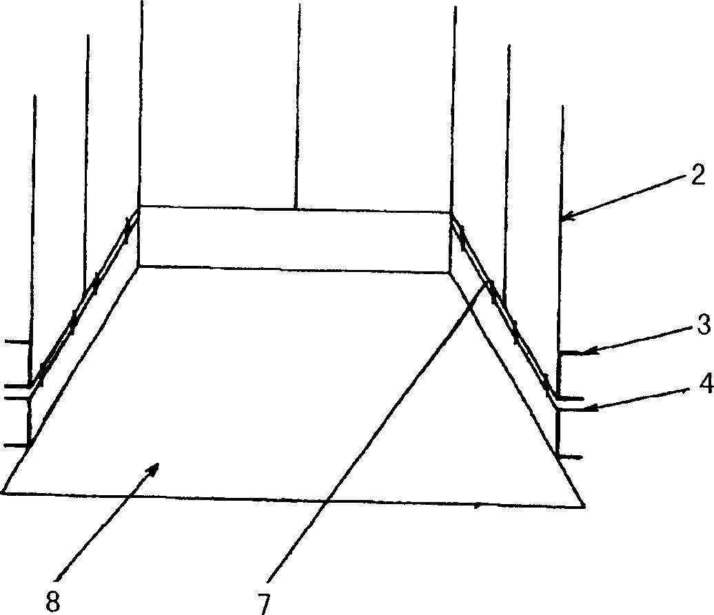
[0020] Such as figure 1 As shown, the elevator car includes: car wall panels 2 , car wall panel reinforcing ribs 3 , skirting boards 4 , ventilation slits 7 and car floor panels 8 .

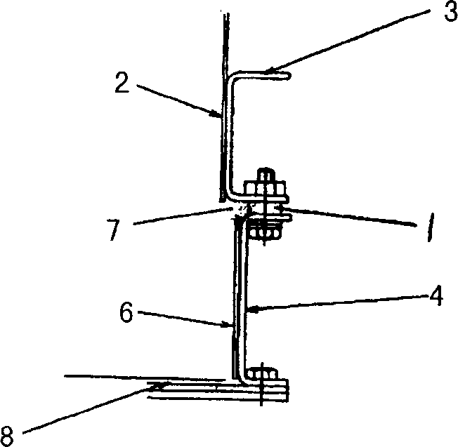
[0021] Such as figure 2 As shown, it includes: car wall plate 2; car wall plate reinforcing rib 3 installed on the back of car wall plate 2, wherein the car wall plate reinforcing rib 3 is to increase the strength of car wall plate 2, and through the car wall plate reinforcing rib 3, the skirting board 4 is arranged on the lower side of the car wall board 2, the car wall board reinforcing rib 3 and the skirting board 4 are connected by threads, and a screw thread is set between the car wall board reinforcing rib 3 and the skirting board 4 Support sleeve 1. Also by threaded connection between skirting board 4 and car bottom panel 8.

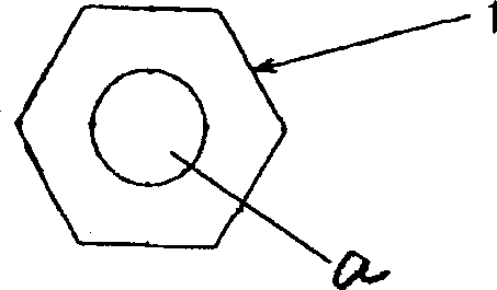
[0022] Such as image 3 As shown, there is a t...


PUM


Abstract

A lower ventilation structure for the cage of elevator has a wall plate, the reinforcing ribs on the back of wall plate, a base board at the low end of wall plate and the ventilating seam between wall plate and base board.

Description

technical field [0001] The invention relates to a ventilation structure of an elevator car, in particular to a ventilation structure arranged at the lower part of the elevator car. Background technique [0002] With the increasing development of the elevator industry, a new standard GB 7588-2003 has been put forward in the elevator industry, in which clause 8.16 stipulates the ventilation requirements of the car. Ventilation holes must be provided at the lower part of the car, and the effective area of ​​the upper and lower ventilation is not large. It should be less than 1% of the effective area of ​​the car. [0003] The current ventilation of the elevator car is generally achieved by setting ventilation holes on the upper part of the car to achieve air convection with the shaft, and there is no ventilation hole on the lower part of the car. The lower part of the car is designed to directly connect the car wall with the skirting board, and ma...

Claims


Application Information

Patent Timeline
Patent Type & Authority Applications(China)
IPC IPC(8): B66B11/02
Inventor 杨天鸣高石茂
Owner TOSHIBA ELEVATOR KK
Why Eureka
Try Eureka