Reception device
一种接收装置、接收信号的技术,应用在接收器监控、空间发射分集、极化/方向分集等方向,能够解决接收指向性模式与发射指向性模式不一致等问题,达到提高指向性形成精度、消除增益偏差的效果
- Summary
- Abstract
- Description
- Claims
- Application Information
AI Technical Summary
Problems solved by technology
Method used
Image

Examples
no. 1 approach
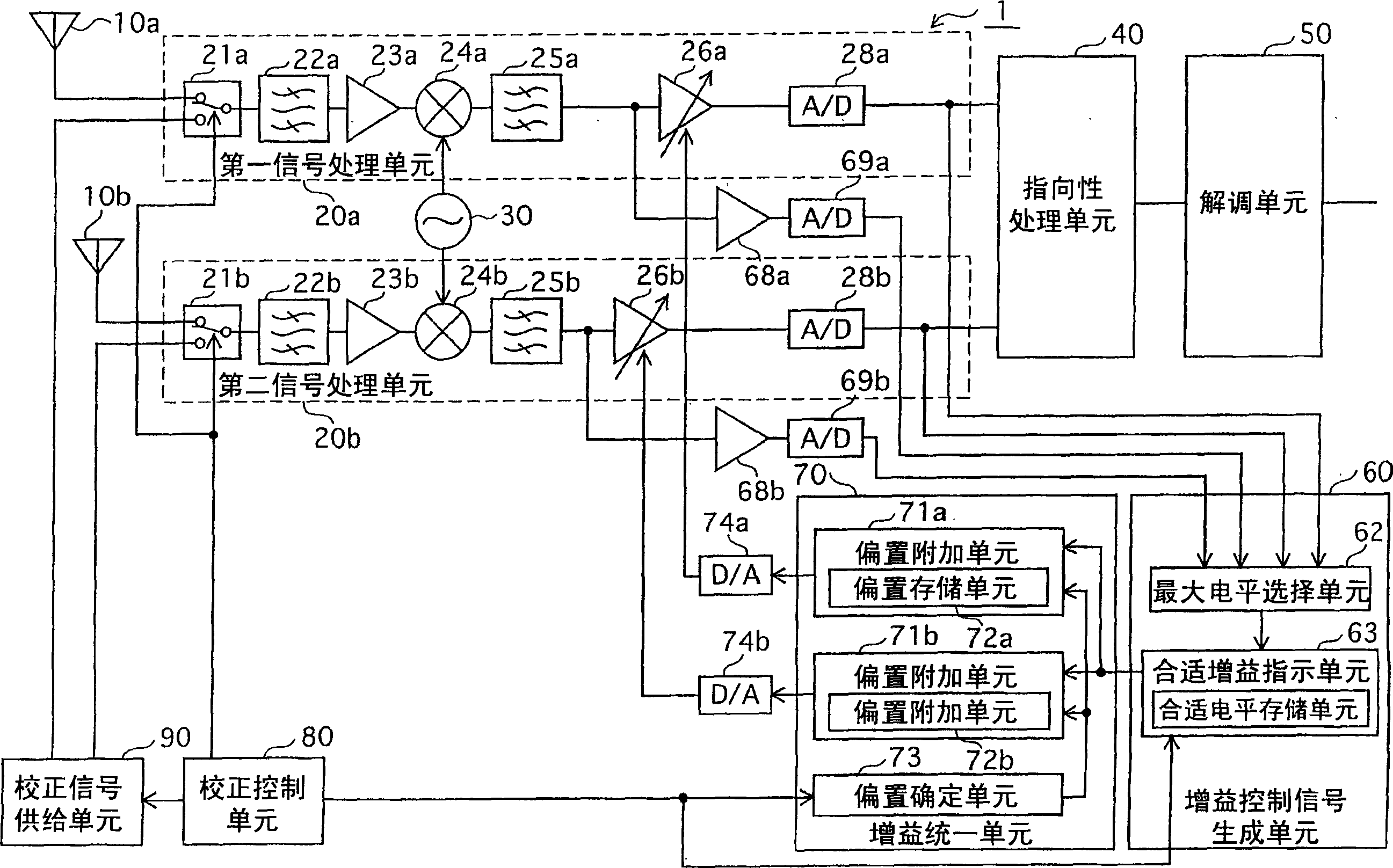
[0028] The receiving device in the first embodiment includes a plurality of antennas, and a signal processing unit that processes received signals of the plurality of antennas, and each signal processing unit includes a variable gain amplifier for performing automatic gain control.
[0029] In this receiving device, the gain control signal is generated by assigning the signal with the highest level among the signals obtained from the respective signal processing units. Then, when using the gain control signal to collectively control the gain of each variable gain amplifier, an offset corresponding to the gain deviation generated by each signal processing unit is added to the gain control signal of each signal processing unit, and the offset is added. The gain control signal controls the gain of the variable gain amplifier on each signal processing unit.
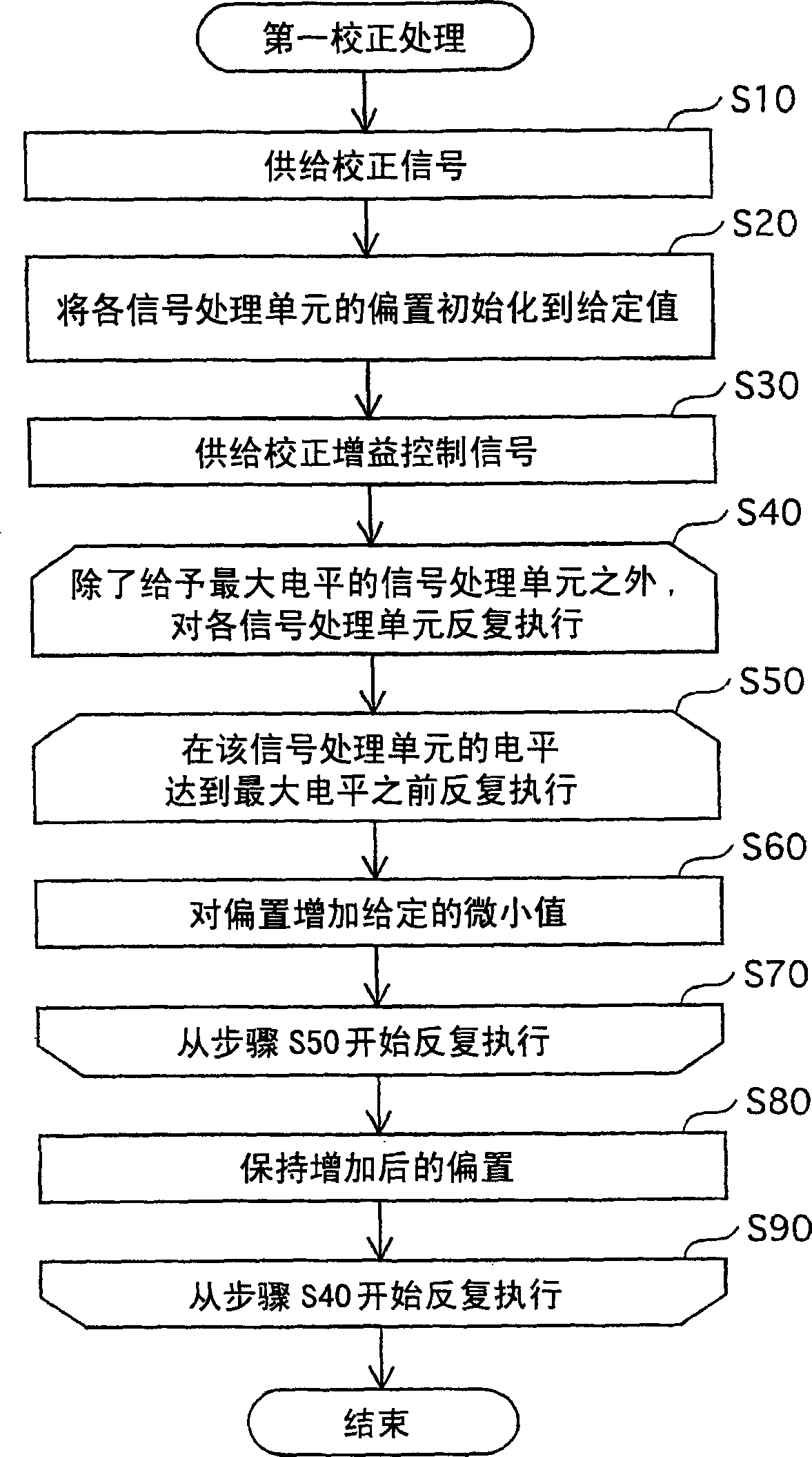
[0030] In addition, in order to achieve the offset of each signal processing unit to correctly offset the deviation of the ...
no. 2 approach
[0061] The receiving apparatus according to the second embodiment is different from the first embodiment in terms of using offsets stored in advance in each signal processing unit in association with a plurality of different reception signal frequencies and a plurality of different gain control signal levels. The receiving device in the mode is different. Hereinafter, the description will be mainly focused on differences from the reception device in the first embodiment.
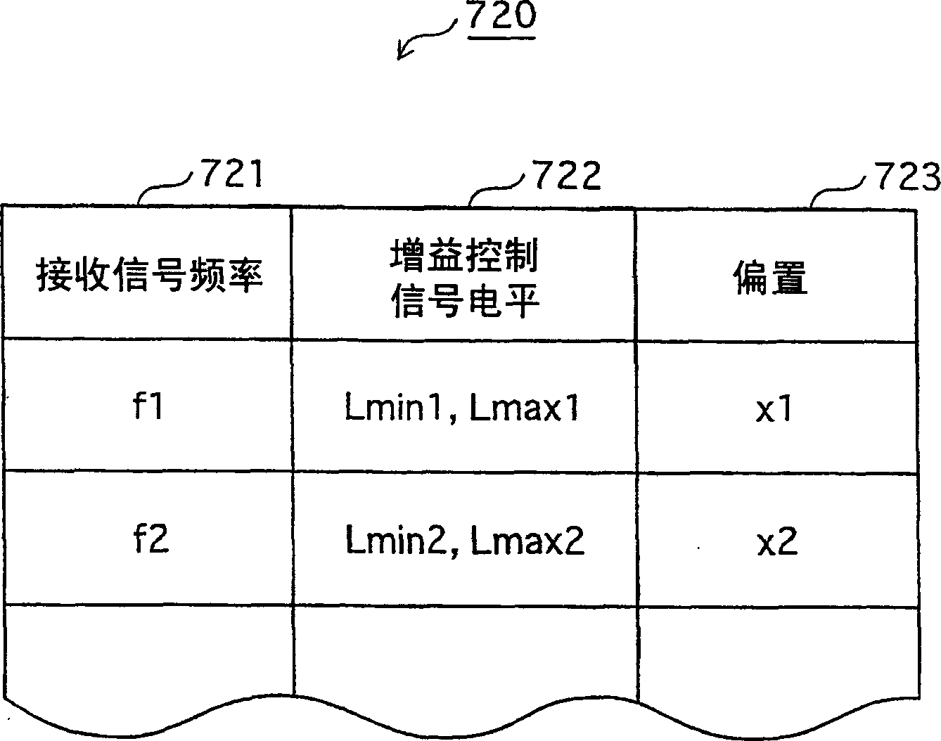
[0062] image 3 It is the offset table 720 set in the offset storage unit of each signal processing unit in the receiving device under the second embodiment, after establishing correspondence between different multiple received signal frequencies and different multiple gain control signal levels memory bias.
[0063] The offset table 720 maintains the carrier frequency of the received signal in the received signal frequency column 721 of each row, and maintains the lower limit value and upper limit value i...
no. 3 approach
[0069] In the receiving apparatus of the third embodiment, unlike a variable gain amplifier for applying AGC (Automatic Gain Control), other variable gain amplifiers for achieving uniform gain of each signal processing unit are inserted in series in each signal processing unit. The aspect of the processing unit is different from that of the receiving device in the first embodiment.
[0070] Figure 5 It is a functional block diagram showing the overall configuration of the receiving device 2 in the third embodiment. The same reference numerals are assigned to the same constituent elements as those of the receiving device 1 according to the first embodiment, and description thereof will be omitted.
[0071] In the receiving device 2, the gain control signal generated by the gain control signal generating unit 60 is converted into an analog voltage signal by a D / A converter without additional bias in order to unify the gain of each signal processing unit, and jointly controls t...
PUM
 Abstract
Description
Claims
Application Information
 - R&D
- Intellectual Property
- Life Sciences
- Materials
- Tech Scout
- Unparalleled Data Quality
- Higher Quality Content
- 60% Fewer Hallucinations
Browse by: Latest US Patents, China's latest patents, Technical Efficacy Thesaurus, Application Domain, Technology Topic, Popular Technical Reports.
© 2025 PatSnap. All rights reserved.Legal|Privacy policy|Modern Slavery Act Transparency Statement|Sitemap|About US| Contact US: help@patsnap.com