Automatic gain control device for electronic endoscope

a gain control device and electronic endoscope technology, applied in the field of electronic endoscope equipment, can solve the problems of deteriorating reproduction image quality, affecting the quality of reproduction images, and not fully exploiting the ability of the ccd to produce quality images

Inactive Publication Date: 2007-07-24
HOYA CORP
View PDF15 Cites 56 Cited by
  • Summary
  • Abstract
  • Description
  • Claims
  • Application Information

AI Technical Summary

Benefits of technology

[0007]Therefore, an object of the present invention is to provide an automatic gain control device that is able to amplify image signals to a proper gain that is based on the saturation voltage characteristics of an imaging device, and further, to provide an electronic endoscope apparatus in which the automatic gain control device is provided.

Problems solved by technology

However, since the saturation voltage for the same type of CCD, manufactured in the same lot, is uneven, a suitable gain for the image signals in the image-signal processing device is different for each of the electronic endoscopes attached to the image-signal processing device.
However, when the gain of an image-signal processing device is preset to the value that covers the minimum saturation voltage for all of the CCDs, image signals from an electronic endoscope with a high output voltage are superfluously amplified by the preset gain and this makes the S / N ratio worse.
Namely, reproduced images deteriorate because of noise even though the image signals are obtained at a sufficiently high level and the ability of the CCD to produce quality images is not fully utilized.

Method used


Image

  • Automatic gain control device for electronic endoscope
  • Automatic gain control device for electronic endoscope
  • Automatic gain control device for electronic endoscope

Examples


first embodiment

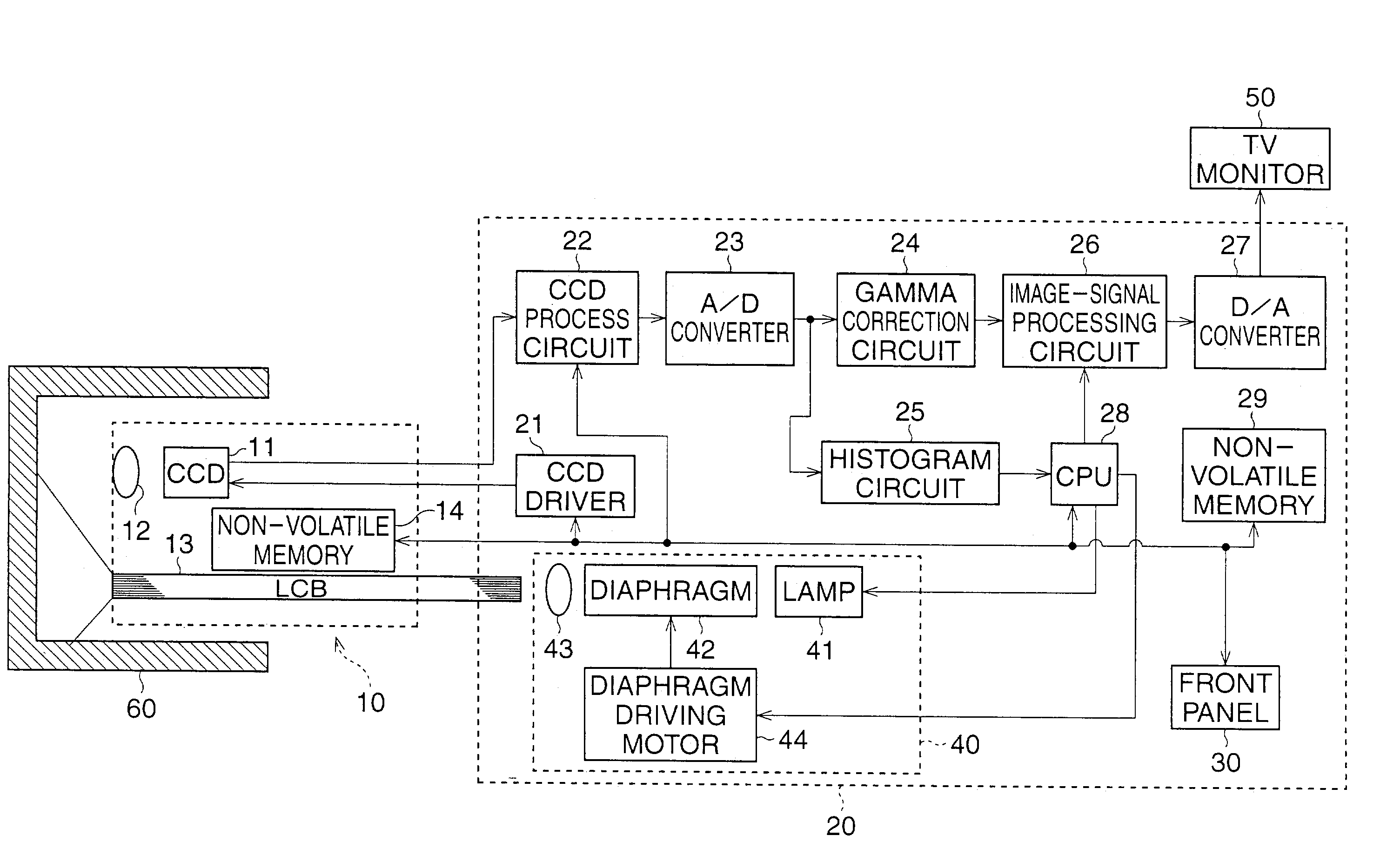
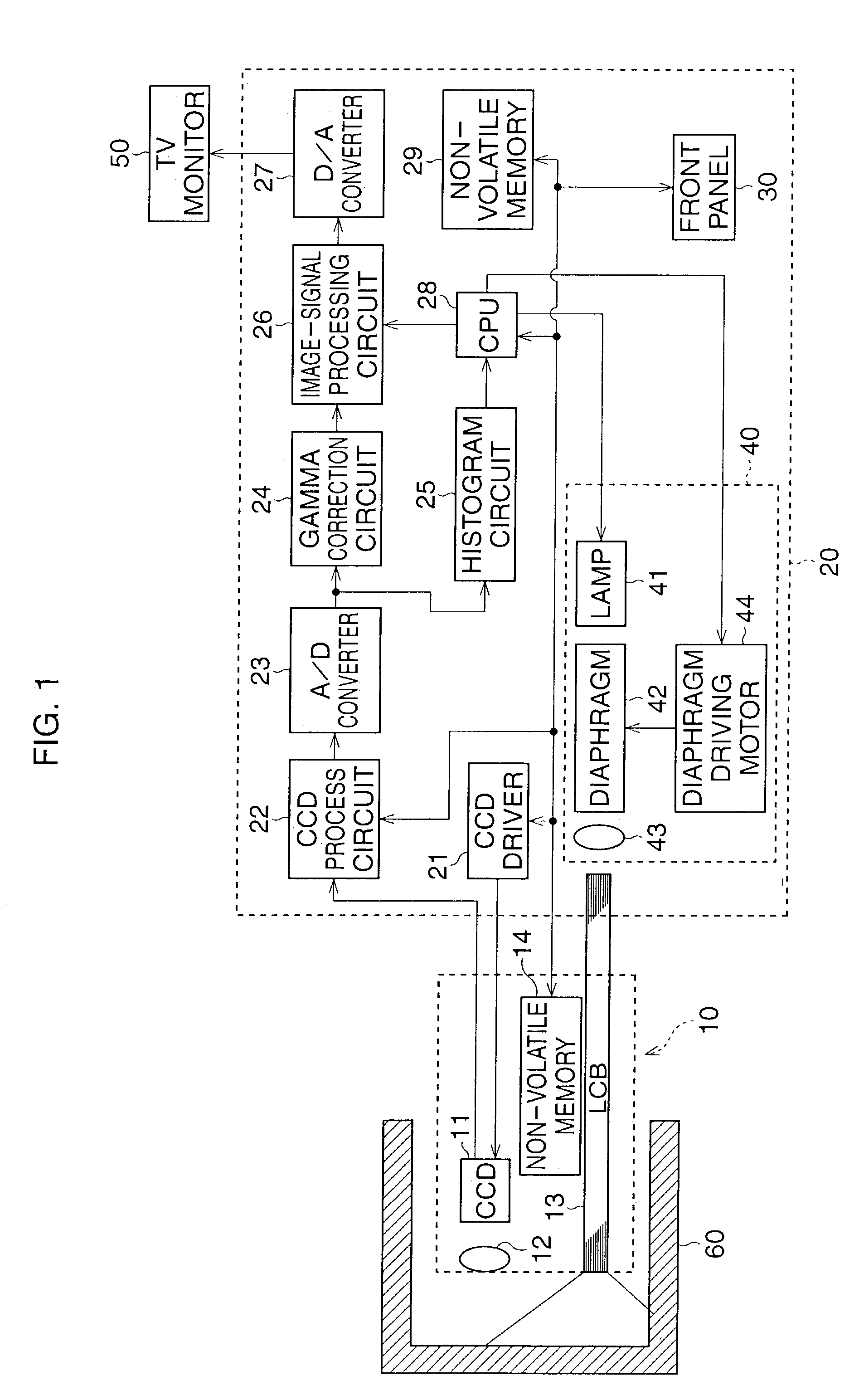
[0023]FIG. 1 is a block diagram of an electronic endoscope system of the present invention. The electronic endoscope apparatus of the present embodiment generally comprise an electronic endoscope 10, an image-processing device 20, and a TV monitor 50. The electronic endoscope 10 is detachably connected to an image-signal processing device 20, and the TV monitor 50 is connected to a video output terminal of the image-signal processing device 20 through a video signal cable. Although in the present embodiment, only the TV monitor 50 is shown as an example of a peripheral device, a video printer, VCR, or computer may also be connected to the image-signal processing device 20.

[0024]The electronic endoscope 10 has an insertion portion that is formed with a flexible conduit. An imaging device, such as a CCD 11, is provided at the distal end of the conduit, so that an image of an internal body or a tube is captured by the CCD 11 through an objective lens 12. Inside the electronic endoscope...

second embodiment

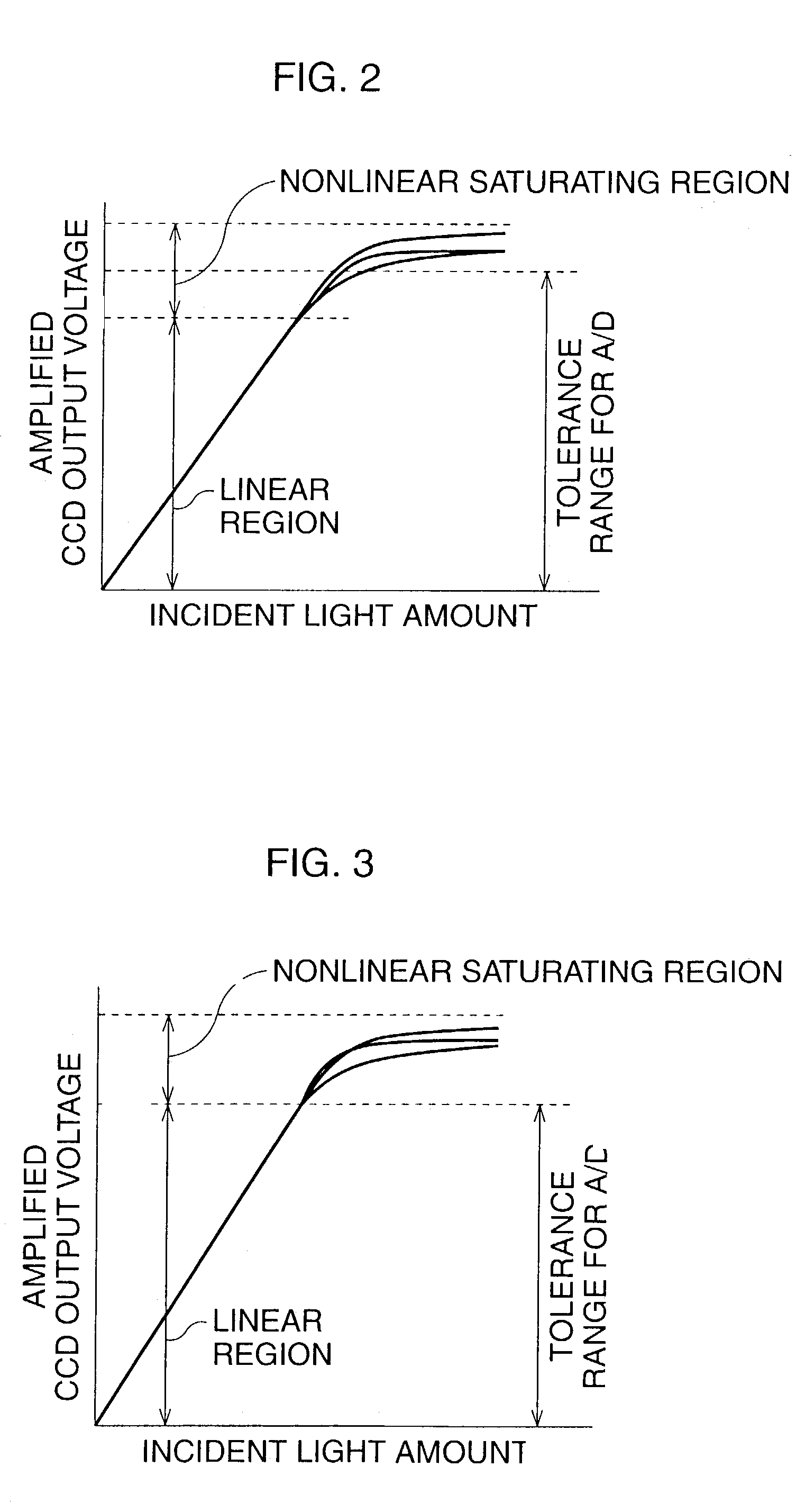
[0049]When it is determined in Step S308 that a pixel with its color difference signal (R-Y) or (B-Y) not equal to the median, exists among the pixels, the gain of the controllable gain amplifier is incremented by one-step in Step S310. Thereby, the linear regions of all the amplified image signals are suitably adjusted to the tolerance range of the A / D converter 23. In Step S311, the value of the gain adjusted in Step S310 is stored in the memory 29 with the model name or the serial number of the electronic endoscope 10, and at the same time, the value of the gain is also stored in the memory 14 of the electronic endoscope 10. Accordingly, the automatic gain control operation program for the second embodiment ends.

[0050]As described above, according to the second embodiment, the same effect as that in the first embodiment can be achieved. Further, in the second embodiment, as an alternative to the luminance signals of the first embodiment, the color difference signals are used for ...


PUM


Abstract

An automatic gain control device for an electronic endoscope is provided and comprises a controllable gain amplifier, an A / D converter, a histogram circuit, and a CPU. The controllable gain amplifier amplifies image signals from an imaging device. Amplified image signals from the controllable gain amplifier are input to the A / D converter. A histogram of the amplified image signals from the controllable gain amplifier is produced by the histogram circuit when an image taken in a white-balance test accessory is taken. By using the CPU, the gain of the controllable gain amplifier is adjusted in accordance with the determination of whether a saturated pixel exists for signals in the tolerance range of the A / D converter, so that a linear region of the image signals from the controllable gain amplifier substantially coincides with the tolerance range.

Description

BACKGROUND OF THE INVENTION[0001]1. Field of the Invention[0002]The present invention relates to an electronic endoscope apparatus that is used for observing an internal organ in a human body, an object inside a duct, and the like.[0003]2. Description of the Related Art[0004]An electronic endoscope apparatus generally comprises an electronic endoscope with a flexible conduit (or insertion portion) which is inserted into a body or a duct, an image-signal processing device that processes image signals from a CCD which is provided at the distal end of the flexible conduit, and an image-indicating device (or a TV monitor) for monitoring images captured by the CCD. Electronic endoscopes are detachable from the image-signal processing device so that a suitable electronic endoscope can be attached to the image-signal processing device as required. When an electronic endoscope is attached to the image-signal processing device, image signals from the electronic endoscope are amplified and ar...

Claims


Application Information

Patent Timeline
Patent Type & Authority Patents(United States)
IPC IPC(8): H04N5/235G02B23/24A61B1/04A61B1/045H04N5/20H04N5/202H04N5/225H04N5/243H04N17/00
CPCH04N5/20H04N5/243A61B1/045H04N5/202H04N17/002H04N2005/2255H04N23/555H04N23/76
Inventor IKETANI, KOHEI
Owner HOYA CORP
Why Eureka
Try Eureka