Attenuation cell with an attenuation factor control device

an attenuation cell and control device technology, applied in the field of analog signal processing circuits, can solve the problems of limited precision and limited precision of known attenuation control cells

Inactive Publication Date: 2007-06-05
ST ERICSSON SA
View PDF7 Cites 0 Cited by
  • Summary
  • Abstract
  • Description
  • Claims
  • Application Information

AI Technical Summary

Benefits of technology

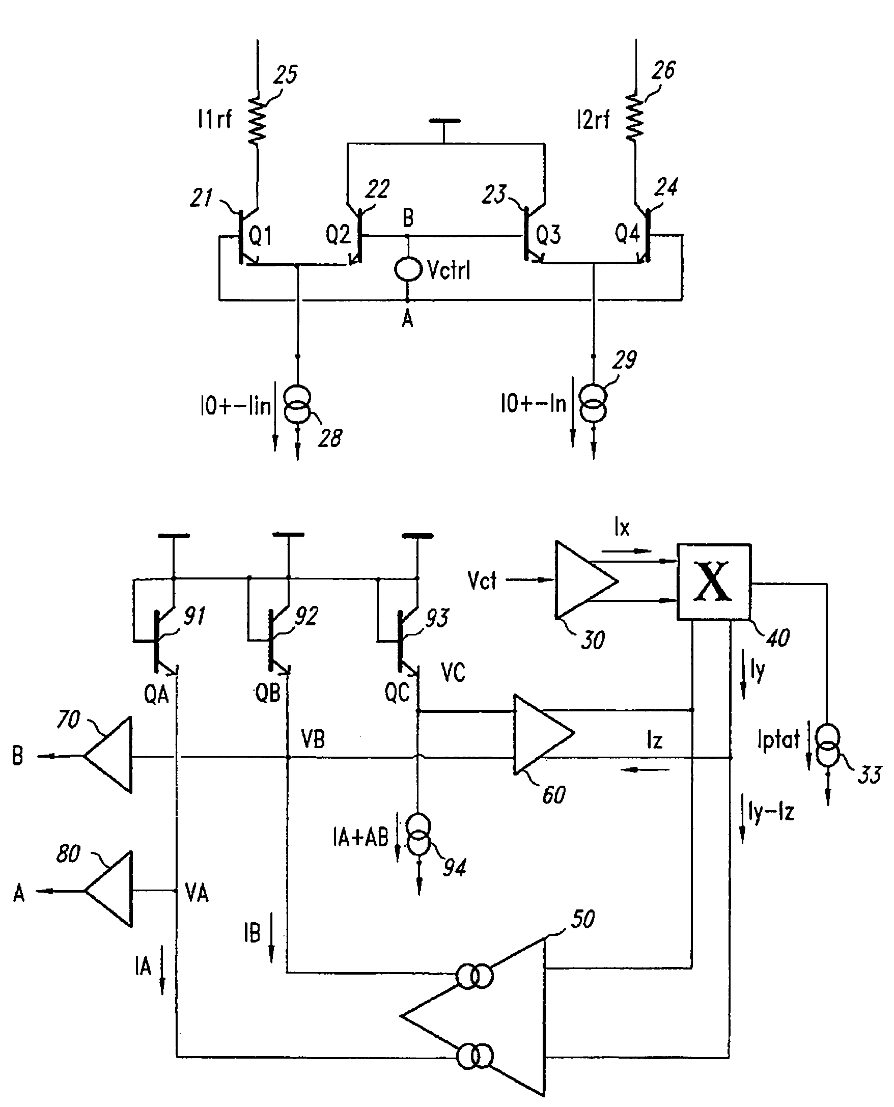
[0011]One embodiment of the present invention provides an attenuation control cell allowing to precisely control a gain, expressed in decibel, from a desired input—input voltage or current.
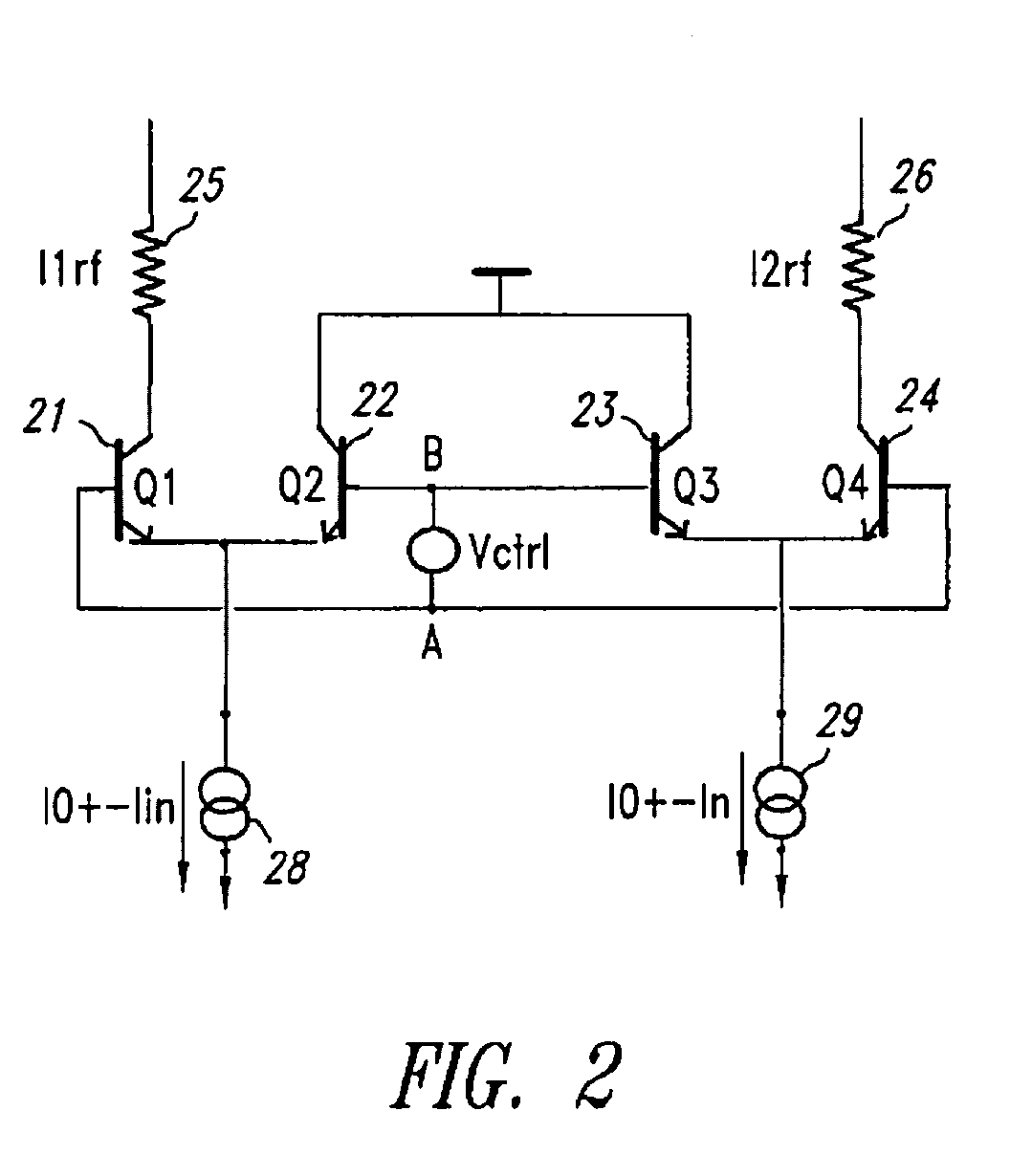
[0013]A gain control device applies a voltage VA−VB between the bases of the two differential pairs and comprises a set of three diodes in which a current IA, a current IB and the sum IA+IB of both preceding currents flow, respectively. The two diodes seeing current IB and IA+IB generate a voltage, respectively VB and VC, and the difference between these two voltages is used to generate a value Iz that is used in a control. Desired input Vct is transformed into information Ix, then into information Iy proportional to absolute temperature T, and an error amplifier uses information Iy−Iz and generates currents IA and IB by minimizing this difference.
[0021]an error amplifier receiving as input error Iy−Iz and generating currents IA and IB in order to minimize said error.

Problems solved by technology

Generally, in known circuits, the linear relation between gain, in decibels, and desired input is established by means of a second order approximation, which leads to very limited precision.
It is observed that known attenuation control cells are limited with regard to the precision of the attenuation factor, which also largely depends on operational temperature.

Method used


Image

  • Attenuation cell with an attenuation factor control device
  • Attenuation cell with an attenuation factor control device
  • Attenuation cell with an attenuation factor control device

Examples


Embodiment Construction

[0030]Embodiments of an attenuation cell with an attenuation factor control device are described herein. In the following description, numerous specific details are given to provide a thorough understanding of embodiments. One skilled in the relevant art will recognize, however, that the invention can be practiced without one or more of the specific details, or with other methods, components, materials, etc. In other instances, well-known structures, materials, or operations are not shown or described in detail to avoid obscuring aspects of the invention.

[0031]Reference throughout this specification to “one embodiment” or “an embodiment” means that a particular feature, structure, or characteristic described in connection with the embodiment is included in at least one embodiment. Thus, the appearances of the phrases “in one embodiment” or “in an embodiment” in various places throughout this specification are not necessarily all referring to the same embodiment. Furthermore, the par...


PUM


Abstract

Attenuation cell comprising first and second differential pairs of bipolar transistors. A gain control device applies a voltage VA−VB between the bases of both differential pairs and comprises a set of three diodes in which a current IA, a current IB and the sum IA+IB of both preceding currents flow, respectively. The two diodes seeing current IB and IA+IB generate a voltage, respectively VB and VC, and the difference between these two voltages is used to generate a value Iz used in a control loop. A desired value Vct is transformed into information Ix, then into information Iy proportional to absolute temperature T, and an error amplifier uses information Iy−Iz and generates currents IA and IB by minimizing this difference.

Description

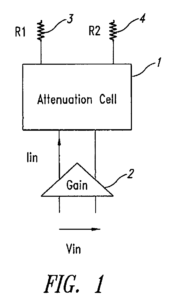
BACKGROUND OF THE INVENTION[0001]1. Field of the Invention[0002]The present disclosure generally relates to analog signal processing circuits and in particular but not exclusively to an attenuation cell having an attenuation factor control device for applying dB-linear control according to a control value, voltage or current.[0003]2. Description of the Related Art[0004]Attenuation cells are frequently used in analog signal processing circuits. When associated with an amplifier, an attenuation cell makes it possible to obtain variable gain, as illustrated in FIG. 1 where a cell 1 is combined with an amplifier 2—of the transconductance type—which receives a differential input signal Vin. By varying the current circulating in the load, made up of two resistors 3 and 4, the gain of the whole circuit can be controlled.[0005]In many applications, it is desirable to have gain that is linear with control, expressed directly in decibels from a desired input, current or voltage. In the most r...

Claims


Application Information

Patent Timeline
Patent Type & Authority Patents(United States)
IPC IPC(8): H03F3/45H03G1/04H03G7/06
CPCH03G1/04H03G7/06
Inventor GRASSET, JEAN-CHARLESBOSSU, FREDERIC
Owner ST ERICSSON SA
Why Eureka
Try Eureka