Receiver with automatic gain control that operates with multiple protocols and method thereof

a receiver and multi-protocol technology, applied in the field of communication receivers, can solve the problems of loss of all or a portion of the modulated information, increase the linearity requirements of the receiver, and increase the complexity of the agc,

Active Publication Date: 2005-03-03
APPLE INC
View PDF11 Cites 58 Cited by
  • Summary
  • Abstract
  • Description
  • Claims
  • Application Information

AI Technical Summary

Problems solved by technology

However, as increasing portions of the information are contained in the amplitude component of the received signal, as indicated by increasing peak-to-average ratios of the received signal, the receiver linearity requirements greatly increase thus necessitating increased AGC complexity.
Compression results in the loss of all or a portion of the amplitude component of the modulated information.
This distortion is particularly detrimental to a received signal containing significant amplitude component within its modulation.
However, in a simplified closed loop control system, slowing down the AGC tracking rate has the undesired effect of increasing the AGC attack time.
Therefore, there exists a paradox in receiver systems, where particular protocols may require fast AGC attack times necessitating high AGC tracking rates, while the highly linear modulation strategy incorporated into the same protocol may require slow AGC tracking rates that would degrade attack times. Previous receivers have attempted to resolve this paradox by focusing on specific protocols and modulation strategies without regard to readily adapting the system to accommodate multiple protocols and modulation types.
AGC strategies are further complicated by protocol requirements necessitating AGC response to both synchronous and asynchronous signals.
Existing systems that are targeted to multiple standards incur significantly increased costs and / or performance degradation due to increased hardware complexity and / or increased system resource demands (i.e. increased host processing resulting in increased power consumption and increased latency in servicing user specific applications).

Method used


Image

  • Receiver with automatic gain control that operates with multiple protocols and method thereof
  • Receiver with automatic gain control that operates with multiple protocols and method thereof
  • Receiver with automatic gain control that operates with multiple protocols and method thereof

Examples


Embodiment Construction

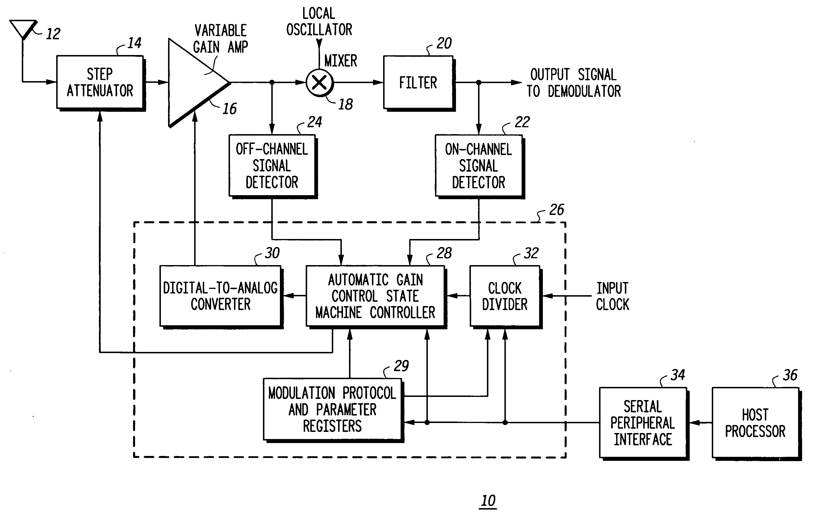
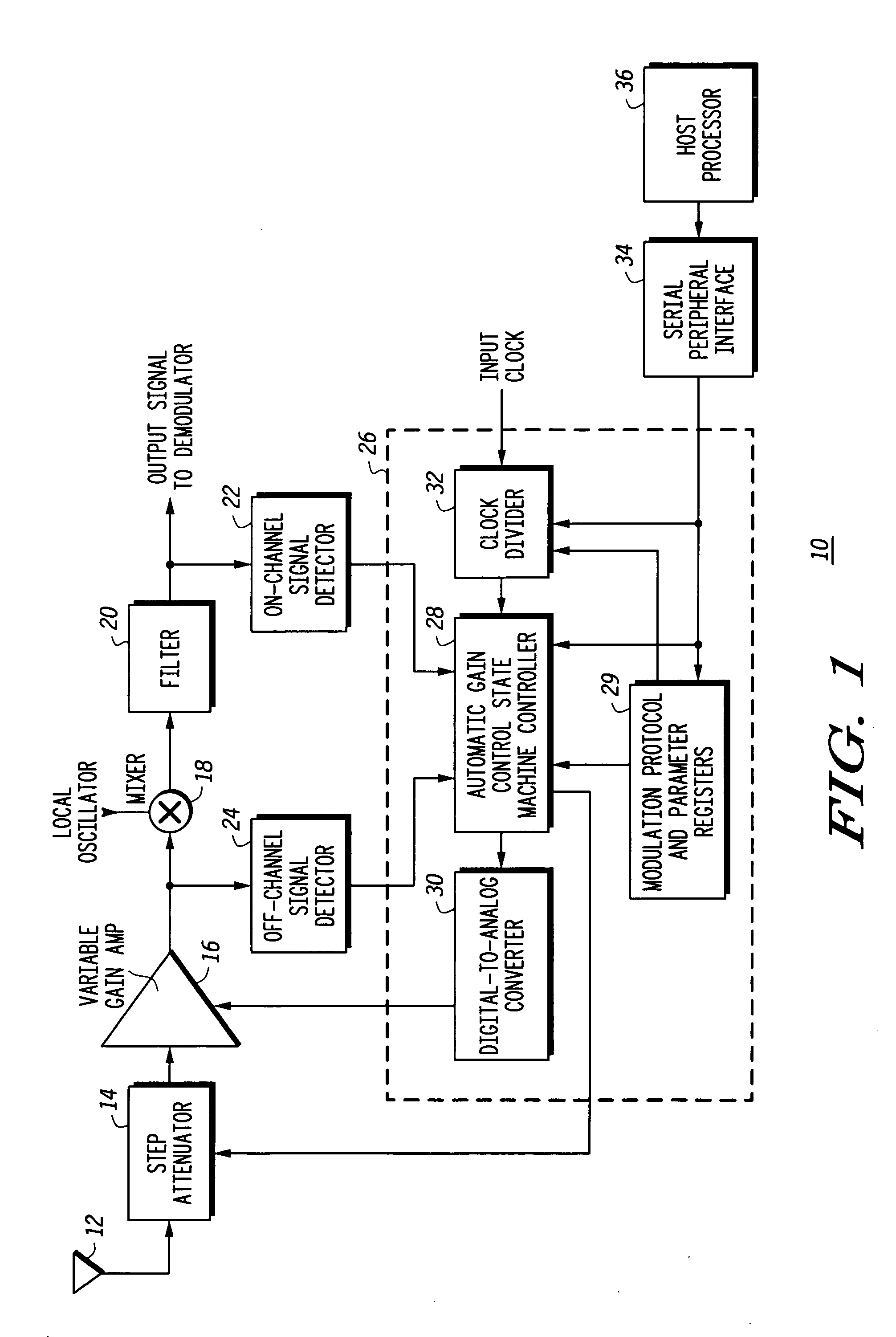
[0016] Illustrated in FIG. 1 is a receiver 10 with automatic gain control for operating with multiple modulation protocols and which interfaces with a host processor 36 through a serial peripheral interface (SPI) 34. For convenience of illustration and emphasis on automatic gain control, all the circuitry associated with a receiver is not illustrated. The receiver 10 has an antenna 12 connected to an input of a step attenuator 14. Step attenuator 14 has an output connected to an input of a variable gain amplifier 16. An output of the variable gain amplifier 16 is connected to a first input of a mixer 18. A second input of mixer 18 is connected to a Local Oscillator (LO) signal. An output of mixer 18 is connected to an input of a filter 20. An output of the filter 20 is connected to an input of an on-channel signal detector 22 and provides an output signal to be connected to a demodulator (not shown). An output of the variable gain amplifier 16 is connected to an input of an off-chan...


PUM


Abstract

An automatic gain control (AGC) method and circuit (10) within a receiver uses a digital state machine (26) to implement the AGC function. independent from interaction with a host processor (36) and for multiple modulation protocols without duplicating circuitry. Modulation protocol and parameters for any of various gain responses are stored in a register (29). Multiple states, each corresponding to a predetermined range of RF input signal strength, are stored in the register. Each state contains parameters that determine a gain control signal for controlling a variable gain amplifier (16). The states are independent and may be selectively disabled to create asymmetric responses. Within any state, an adaptable number of iterations may be set to implement a different update rate or step size after a predetermined number of closed loop gain change iterations has not resulted in a transition to a state that represents a desired output gain.

Description

FIELD OF THE INVENTION [0001] This invention relates generally to communication receivers, and more specifically, to automatic gain control (AGC) in a receiver. BACKGROUND OF THE INVENTION [0002] Radio Frequency (RF) receivers typically incorporate Automatic Gain Control (AGC) circuitry to provide proper conditioning of the received RF input power such that the received signal is kept within the usable dynamic range of the receiver. The information embedded in the received signal is transported using one of many different modulation schemes wherein the information may be contained in the frequency or phase of the received signal (e.g. FM, PM, FSK, PSK, etc.), in the amplitude of the received signal (eg. AM), or in both the amplitude and phase of the received signal (eg. QAM). Receiver AGC requirements are driven by several modulation and protocol parameters including, but not limited to, peak-to-average power ratio of the modulation, demodulator dynamic range limitations, analog gai...

Claims


Application Information

Patent Timeline
Patent Type & Authority Applications(United States)
IPC IPC(8): H03G3/00H03G3/20H03G3/30H04L27/08
CPCH03G3/001H03G3/3078H03G3/3052
Inventor RUELKE, CHARLES R.BEN-AYUN, MOSHEGRAHAM, DAVID J.ROZENTAL, MARK
Owner APPLE INC
Why Eureka
Try Eureka