Threshold on unblocking a processing node that is blocked due to data packet passing

A technology of threshold and count value, applied in the threshold field of unblocking processing nodes blocked due to data packet transmission, which can solve problems such as deadlocks

Inactive Publication Date: 2006-06-07
KONINKLIJKE PHILIPS ELECTRONICS NV
View PDF0 Cites 4 Cited by
  • Summary
  • Abstract
  • Description
  • Claims
  • Application Information

AI Technical Summary

Problems solved by technology

[0015] - Thresholds that are too high

Method used


Image

  • Threshold on unblocking a processing node that is blocked due to data packet passing
  • Threshold on unblocking a processing node that is blocked due to data packet passing
  • Threshold on unblocking a processing node that is blocked due to data packet passing

Examples


Embodiment Construction

[0028] The system and method of the present invention reduce the number of environment switches that are the result of passing packets to higher priority flow components in a system that has a preemptive priority based on a scheduler. The reduction in the number of environment switches generally results in better performance at the expense of increased latency.

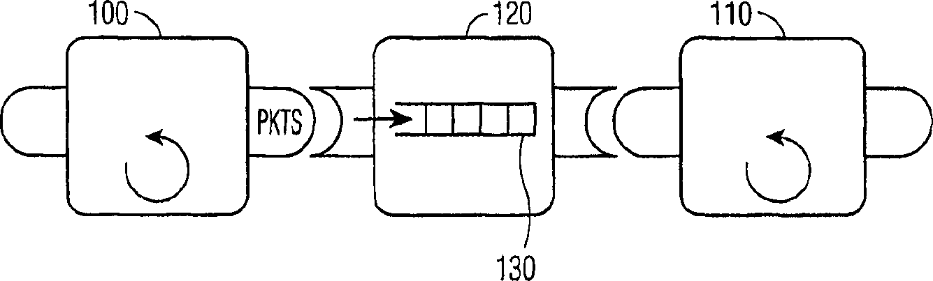
[0029] In a preferred embodiment, the buffer threshold is a mechanism that delays the signaling of blocked consumer components until sufficient packets are available in the buffer, that is, the threshold amount of packets appears in the buffer, The blocked consumer component waits for the packet. When the threshold of the buffer is set to x, only when x packets are available in the buffer, the waiting, i.e. blocked component associated with that buffer is signaled.

[0030] figure 1 Illustrated are low-priority producer components 100 that are all located on the same processor and connected to high-priority consumer com...


PUM


Abstract

A threshold mechanism is provided so that producers and corresponding consumers executing on the same resource (eg, CPU) can switch contexts between them in a manner that reduces the overall number of such context switches. The threshold mechanism is associated with a buffer into which a producer stores packets that reach a specified threshold before allowing consumers to delete packets. The buffer has an upper limit on being able to store in relation to the number of packets in the buffer. When no more packets are produced, a flush empties the buffer of any remaining packets. This reduction in the overall number of context switches generally results in better performance at the expense of more latency.

Description

Technical field [0001] The present invention relates to a threshold for controlling data packet exchange between producers and consumers residing on the same CPU. More specifically, the present invention relates to software flow based on processing node graphs, and is a threshold system for unblocking processing nodes that are blocked due to data packet transfer between two processing nodes residing on the same CPU And method. Background technique [0002] Software flow is based on processing node graphs, where communication between nodes is carried out using discrete data packets. Nodes actively transmit packets from their input edge to their output edge, thereby allowing data to flow through the graph. Each packet starts at the source node and ends at the sink node through the graph according to a certain path. [0003] Two processing nodes running on the same resource (for example, CPU) cannot truly run in parallel. Instead, the resource switches between the execution of the t...

Claims


Application Information

Patent Timeline
IPC IPC(8): G06F9/46
CPCG06F9/461G06F9/485G06F9/544G06F9/46
Inventor E·G·P·范多恩H·C·W·范希斯奇
Owner KONINKLIJKE PHILIPS ELECTRONICS NV
Why Eureka
Try Eureka