Surface roughness measuring method and apparatus and turbine deterioration diagnostic method

A technology of surface roughness and measurement method, applied in measurement devices, mechanical equipment, engine components, etc., can solve problems such as expensive, large lens parts, and optical devices susceptible to vibration.

Inactive Publication Date: 2006-06-14
KK TOSHIBA
View PDF3 Cites 5 Cited by
  • Summary
  • Abstract
  • Description
  • Claims
  • Application Information

AI Technical Summary

Problems solved by technology

[0012] On the other hand, optical devices, such as digital microscopes, have been greatly developed in recent years, but it is still expensive
In addition, its lens section is large, so it has the disadvantage of requiring a sufficient space allowance to install the lens section around the object to be measured
In addition, the optics are easily affected by vibrations during the measurement, so the measurement conditions are very limited

Method used


Image

  • Surface roughness measuring method and apparatus and turbine deterioration diagnostic method
  • Surface roughness measuring method and apparatus and turbine deterioration diagnostic method
  • Surface roughness measuring method and apparatus and turbine deterioration diagnostic method

Examples


no. 1 example

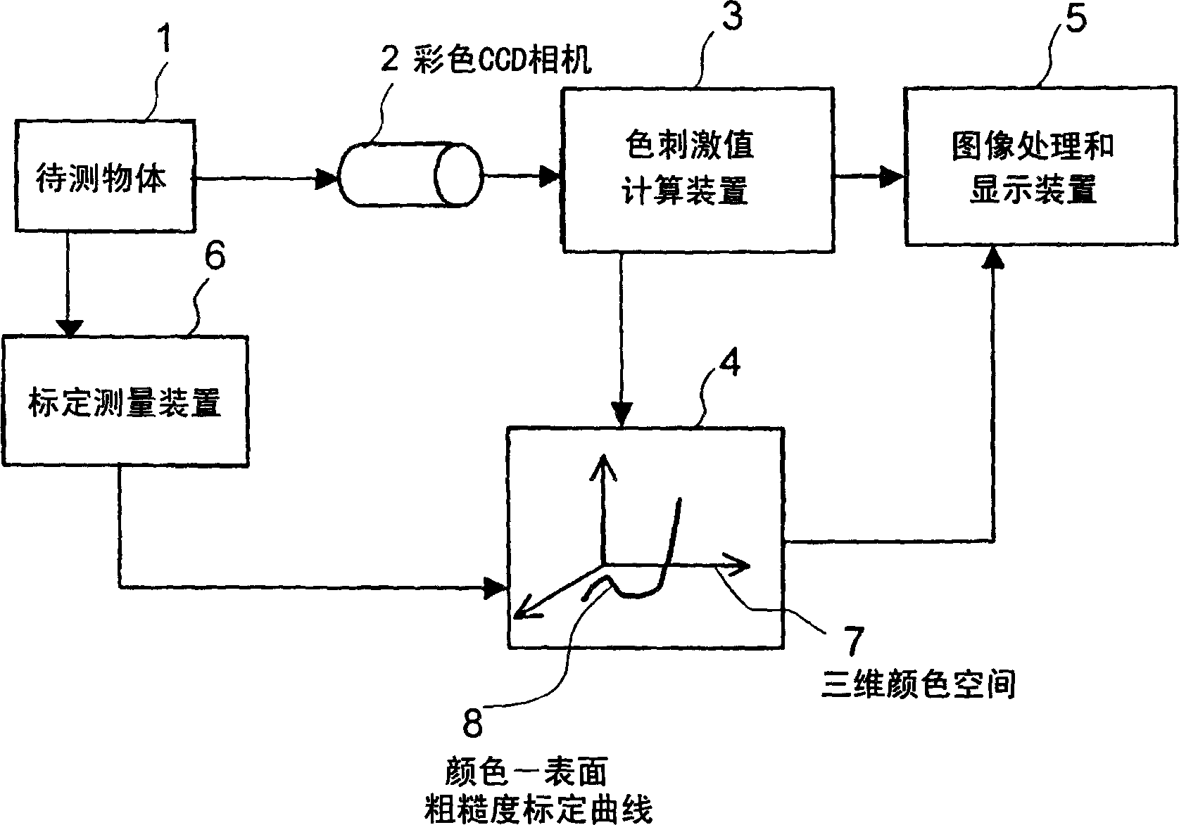
[0035] figure 2 is a block diagram showing a surface roughness measuring device according to a first embodiment of the present invention. This embodiment comprises color CCD (charge-coupled device) camera 2, color stimulus value calculation device 3, database 4, graphics processing and display unit 5 and calibration measurement device 6, wherein color CCD camera 2 is a color imaging device, and it is installed on the The opposite side of the measuring object 1 such as a turbine blade.

[0036] As the color CCD camera 2, a digital still camera or a digital television camera for easy data transfer with an image processing and display device 5 such as a personal computer is used. The color CCD camera 2 includes many pixels, and acquires color image information of the surface of the object 1 to be measured, such as a turbine blade. The color stimulus value calculation section 3 performs various image processing such as noise processing and averaging processing for color image i...

no. 2 example

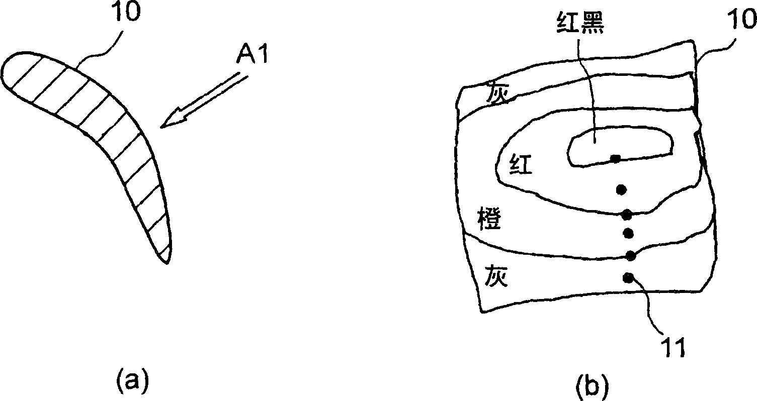
[0043] Figure 4 is schematically shown when passing through the color CCD camera 2 pairs of figure 1 The correspondence of pixels 12 to typical measuring points 11 is shown for measurements taken on the backside of a turbine blade 10 . exist Figure 4 Among them, (a) is a graph showing a state where the axis of the coordinate system is set on the surface of the turbine blade 10, and (b) is a graph showing a state where pixels are set in (a). Suppose the backside of the turbine blade 10 is measured at pixel 100(X)×100(Y), and as a typical measuring point 11 on the backside of the blade, for example, the gray part 11-1 corresponds to the pixel position (X, Y ) = the area at (80, 10). The color information (for example, red, green and blue values) of the pixel area is acquired and recorded by the color CCD camera 2 and the color stimulus value calculation device 3 . When the region extends across multiple pixels, red, green and blue values ​​corresponding to each pixel are ...

no. 3 example

[0047] Figure 6 The database shown in uses the red, green and blue values ​​as the tristimulus values, and forms the RGB space as the three-dimensional space 7 constituted by the axes of the coordinate system of the red, green and blue color stimulus values, and relies on The red, green and blue values ​​of the surface color that vary depending on the surface roughness of the object 1 to be measured are plotted in the space. Here, mark O denotes data obtained by interpolation with a predetermined roughness interval. In the second embodiment shown above Figure 5 In , the relationship between red, green, blue values ​​and surface roughness is reasonably arranged in two-dimensional space, however in Figure 6 In , the exact same data is rationally rearranged in three-dimensional space. exist Figure 6 In , point A represents the position where the surface roughness is the smallest, and point D represents the position where the surface roughness is the largest. here, Figu...


PUM


Abstract

A surface roughness measuring method includes measuring the surface roughness and surface color image information of a plurality of typical measuring points on the surface of a first object to be measured, and preparing calibration information indicating Information on the relationship between chromatic stimulus values ​​and surface roughness. The surface roughness measurement method further includes acquiring surface color image information of a plurality of measuring points on the surface of the second object to be measured, obtaining color stimulus values ​​from the surface color image information of the measuring points, and using the calibration information to map the measuring points The color stimulus value is converted into the surface roughness of the measuring point, and the surface roughness of the measuring point of the second object to be measured is displayed as surface information.

Description

[0001] Related Application Cross Reference [0002] This application is based on and claims priority from a prior Japanese Patent Application No. 2004-358510 filed on December 10, 2004; the entire contents of this prior application are hereby incorporated by reference. technical field [0003] The present invention relates to a method and apparatus for measuring surface roughness, and a method for diagnosing deterioration of a turbine, and more particularly, to a method and apparatus for measuring surface roughness for effectively and accurately measuring The surface roughness of various components, and a turbine degradation diagnosis method for accurately diagnosing the performance degradation of a turbine based on the measured surface roughness. Background technique [0004] In high temperature fluid machines as well as steam turbines and gas turbines, elements such as blades are thermally damaged due to long-term exposure to high temperature environments, and there arises...

Claims


Application Information

Patent Timeline
Patent Type & Authority Applications(China)
IPC IPC(8): G01B11/30F01D5/00
CPCG01B11/303
Inventor 松田寿川上宏猪亦麻子大友文雄川岸裕之
Owner KK TOSHIBA
Why Eureka
Try Eureka