Movable contact unit and panel switch using same

A technology of moving contact and contact body, which is used in electrical switches, moving contacts, metal foil contacts, etc.

Inactive Publication Date: 2006-06-14
PANASONIC CORP
View PDF1 Cites 2 Cited by
  • Summary
  • Abstract
  • Description
  • Claims
  • Application Information

AI Technical Summary

Problems solved by technology

Therefore, although the above-mentioned conventional method of corresponding to the miniaturization of the movable contact body and the panel switch is a simple and useful countermeasure, it is limited to a certain degree of miniaturization.

Method used


Image

  • Movable contact unit and panel switch using same
  • Movable contact unit and panel switch using same
  • Movable contact unit and panel switch using same

Examples


Embodiment Construction

[0024] Hereinafter, embodiments of the present invention will be described using the drawings.

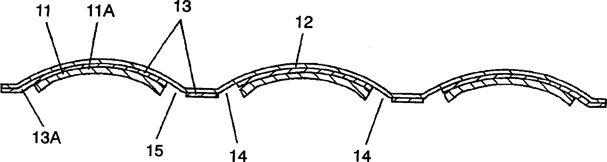
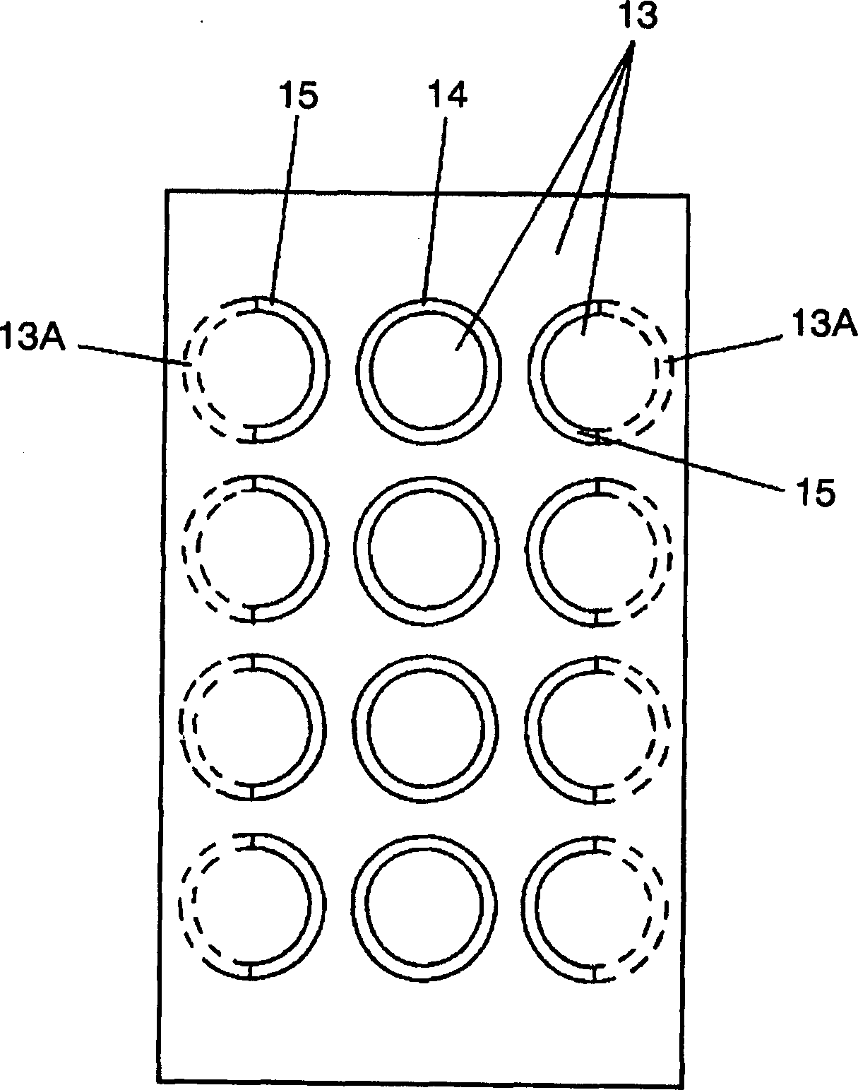
[0025] figure 1 is a sectional view of a movable contact body according to an embodiment of the present invention, figure 2 is a view of the lower surface of the substrate.

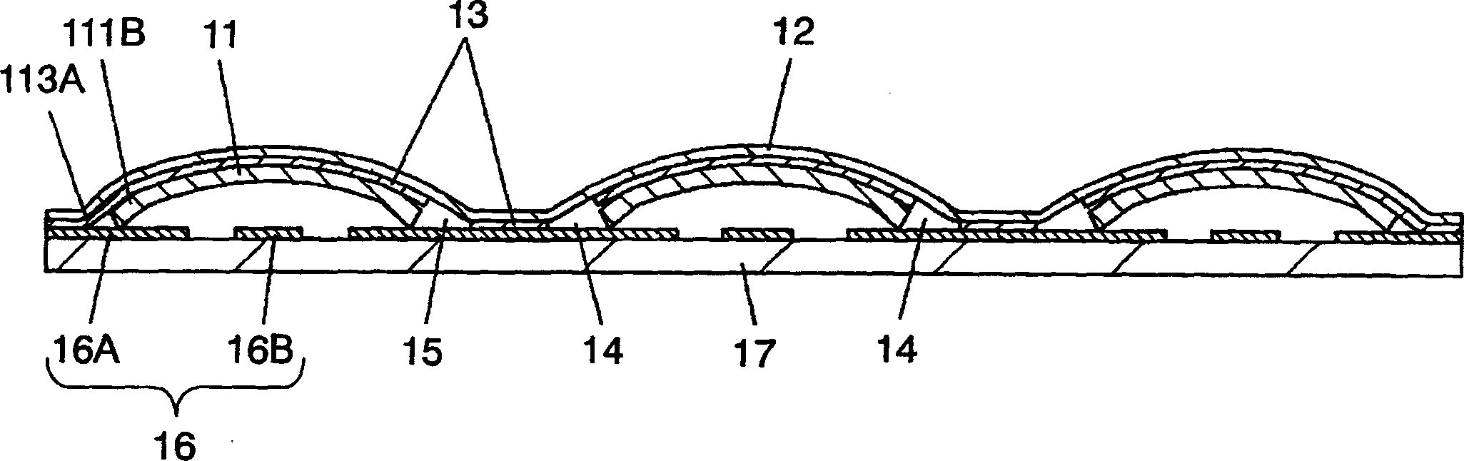
[0026] Such as figure 1 as well as figure 2 As shown, the movable contact body includes a movable contact 11 and a substrate 12 . The movable contact 11 is made of an elastic thin metal plate. The movable contact 11 is the same as the conventional structure, and its outer shape is circular, and the lower part is open, and the upper part is convex. The substrate 12 is made of an insulating film. The adhesive 13 is applied by printing on almost the entire lower surface of the substrate 12 . The upper surface of the dome-shaped apex portion 11A of each movable contact 11 is adhered and held with an adhesive 13 . A plurality of movable contacts 11 are arranged at predetermined positions on the substrat...


PUM


Abstract

A small movable contact unit and a panel switch which prevent peeling from an edge even though the width between the edge of a base sheet and a movable contact is narrowed. The movable contact unit includes the movable contact and base sheet. The movable contact has a round dome shape and is made of a resilient metal sheet. The base sheet is an insulating film which adheres a dome tip of the movable contact with an adhesive applied to its undersurface for holding the movable contact at a predetermined position. A supplementary adhesive is applied to a ring non-adhesive area of the movable contact disposed near the edge of the base sheet at a portion toward the edge of the base sheet. Accordingly, the movable contact disposed near the edge is adhered to and held by the base sheet using the adhesive including the supplementary adhesive.

Description

technical field [0001] The present invention relates to a movable contact body for a panel switch constituting an operation panel or the like of various electronic devices, and a panel switch constituted using the contact body. Background technique [0002] In recent years, portable electronic devices such as mobile phones and PDAs (Personal Digital Assistants) are widely used. These electronic devices are being miniaturized in order to improve portability, etc., and panel switches used in the operation panel portion thereof are also required to be reduced in size. use Figure 4 ~ Figure 6 A conventional movable contact body used in such a panel switch and a panel switch configured using the contact body will be described. Figure 4 is a sectional view of a conventional movable contact body, Figure 5 is an exploded oblique view of the figure, Image 6 It is a cross-sectional view of a panel switch constructed using this movable contact body. [0003] exist Figure 4 as...

Claims


Application Information

Patent Timeline
Patent Type & Authority Applications(China)
IPC IPC(8): H01H13/00H01H13/12H01H13/702
CPCH01H13/7006H01H2203/032H01H2203/038H01H2205/026Y10T29/49105
Inventor 濑良直树古山博通
Owner PANASONIC CORP
Why Eureka
Try Eureka