Rectilinear ion trap and mass analyzer system and method

A mass analyzer, ion trap technology, applied in mass spectrometers, trajectory-stabilized spectrometers, dynamic spectrometers, etc., can solve complex problems

Inactive Publication Date: 2006-06-14
PURDUE RES FOUND INC
View PDF4 Cites 25 Cited by
  • Summary
  • Abstract
  • Description
  • Claims
  • Application Information

AI Technical Summary

Problems solved by technology

All of the above ion traps, with the exception of cylindrical ion traps, require precise mechanical processing such as

Method used


Image

  • Rectilinear ion trap and mass analyzer system and method
  • Rectilinear ion trap and mass analyzer system and method
  • Rectilinear ion trap and mass analyzer system and method

Examples


Embodiment Construction

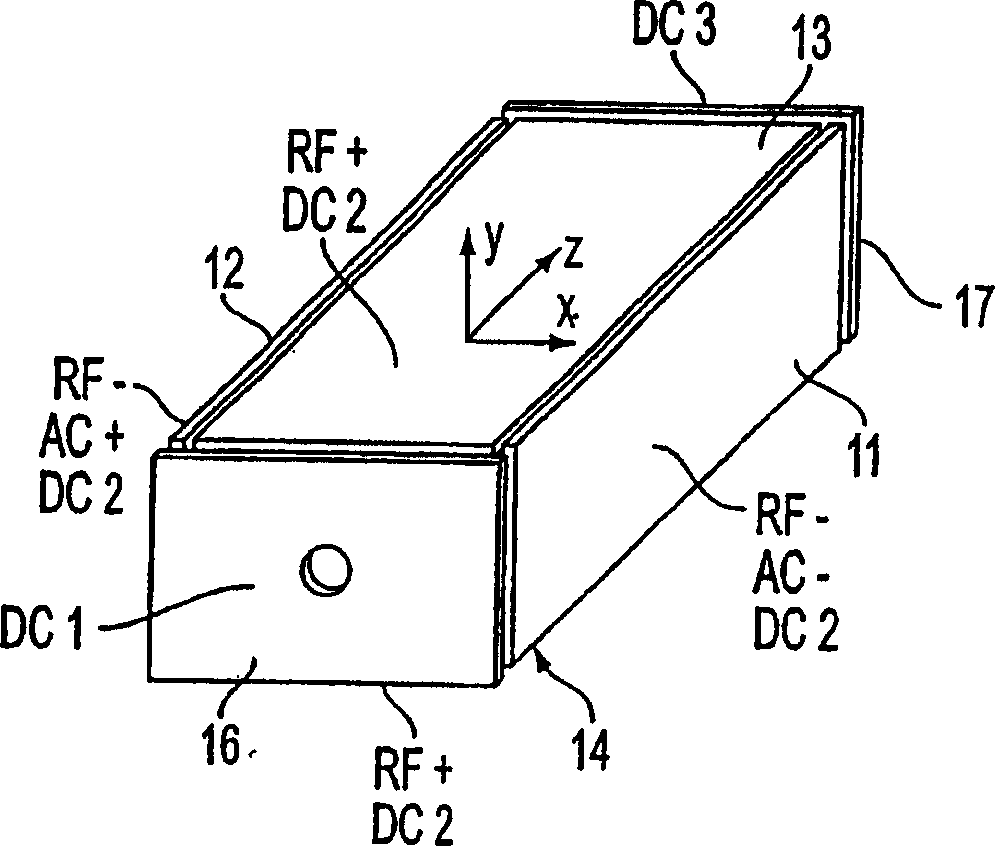
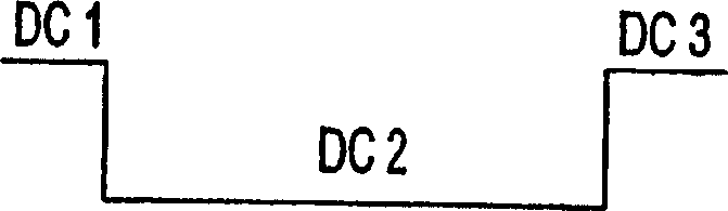
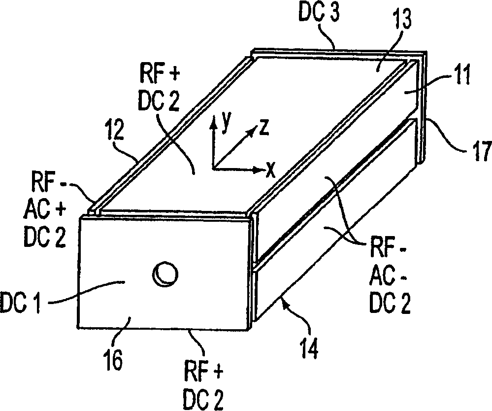
[0042]Figures 1-4 illustrate four linear ion trap geometries and as possible DC, AC and RF voltages applied to the electrode plates to trap and analyze ions. The trapping volume is defined by x and y pairs of spaced planar or planar RF electrodes 11, 12 and 13, 14 in the zx and zy planes. Ions are trapped in the z direction, Figures 1 and 2, by a DC voltage applied to planar or plate end electrodes 16, 17 arranged in the xy plane at the spaced ends of the trapping volume defined by the x,y pair of plates , or in FIG. 3 by a DC voltage applied together with RF to the components 18, 19, where each component 18, 19 comprises several pairs of planar or plate electrodes 11a, 12a and 13a, 13b. In Fig. 4, in addition to the RF section, planar or plate electrodes 16, 17 may be added. The DC trapping voltage is shown for each of the geometries in Figures 1b, 2b, 3b and 4b. Ions are trapped in the x, y direction by a quadrupole RF field generated by an RF voltage applied to the plate....


PUM


Abstract

A new shape ion trap and its use as a mass spectrometer are described. Ion traps can be combined linearly and in parallel to form systems for mass storage, analysis, fragmentation, partitioning, and the like. Ion traps have a simple rectilinear geometry and high trapping capacity. It is operable to provide mass analysis both in a mass selective stable mode and in a mass selective unstable mode. Arrays of multiple ion traps allow the application of a combination of multiple gas phase processes to trapped ions to achieve high sensitivity, high selectivity, and/or higher throughput in ion analysis.

Description

[0001] This application claims priority to Provisional Application Serial No. 60 / 439,350 filed January 10,2003. technical field [0002] The present invention generally relates to an ion trap and an ion trap mass analyzer, in particular to a linear ion trap and a mass analyzer using the linear ion trap. Background technique [0003] A three-dimensional ion trap with a quadrupole field in both r and z (in a polar coordinate system) exerts a linear force on the ions and can be used as an ion trap for ions with a wider or narrower range of mass / charge ratios. The shape of the field is usually determined by a set of three electrodes consisting of a ring electrode and two hyperbolic end cap electrodes. Such a device is called a Paul or quadrupole ion trap. In a simpler alternative, cylindrical ion traps (CITs), the inner surface of the ring is cylindrical and the end caps are flat. [0004] Paul traps and cylindrical ion traps are known to have some disadvantages. They include...

Claims


Application Information

Patent Timeline
IPC IPC(8): H01J49/42
Inventor 罗伯特·G·库克斯欧阳政
Owner PURDUE RES FOUND INC
Why Eureka
Try Eureka