Swinging discharge device of industrial furnace

A technology of discharging device and industrial furnace, applied in furnaces, furnace components, lighting and heating equipment, etc., can solve the problems of high equipment failure rate, high energy consumption, low calcination efficiency, etc., and achieve high combustion efficiency and energy saving. , the effect of temperature stabilization

Active Publication Date: 2006-06-21
SHANXI KWONG FUK ENG
View PDF1 Cites 0 Cited by
  • Summary
  • Abstract
  • Description
  • Claims
  • Application Information

AI Technical Summary

Problems solved by technology

[0003] The invention provides a swing-type industrial furnace discharge device for the problems of low calcination efficiency, high equipment failure rate and high energy consumption in the prior art.

Method used


Image

  • Swinging discharge device of industrial furnace
  • Swinging discharge device of industrial furnace
  • Swinging discharge device of industrial furnace

Examples


Embodiment Construction

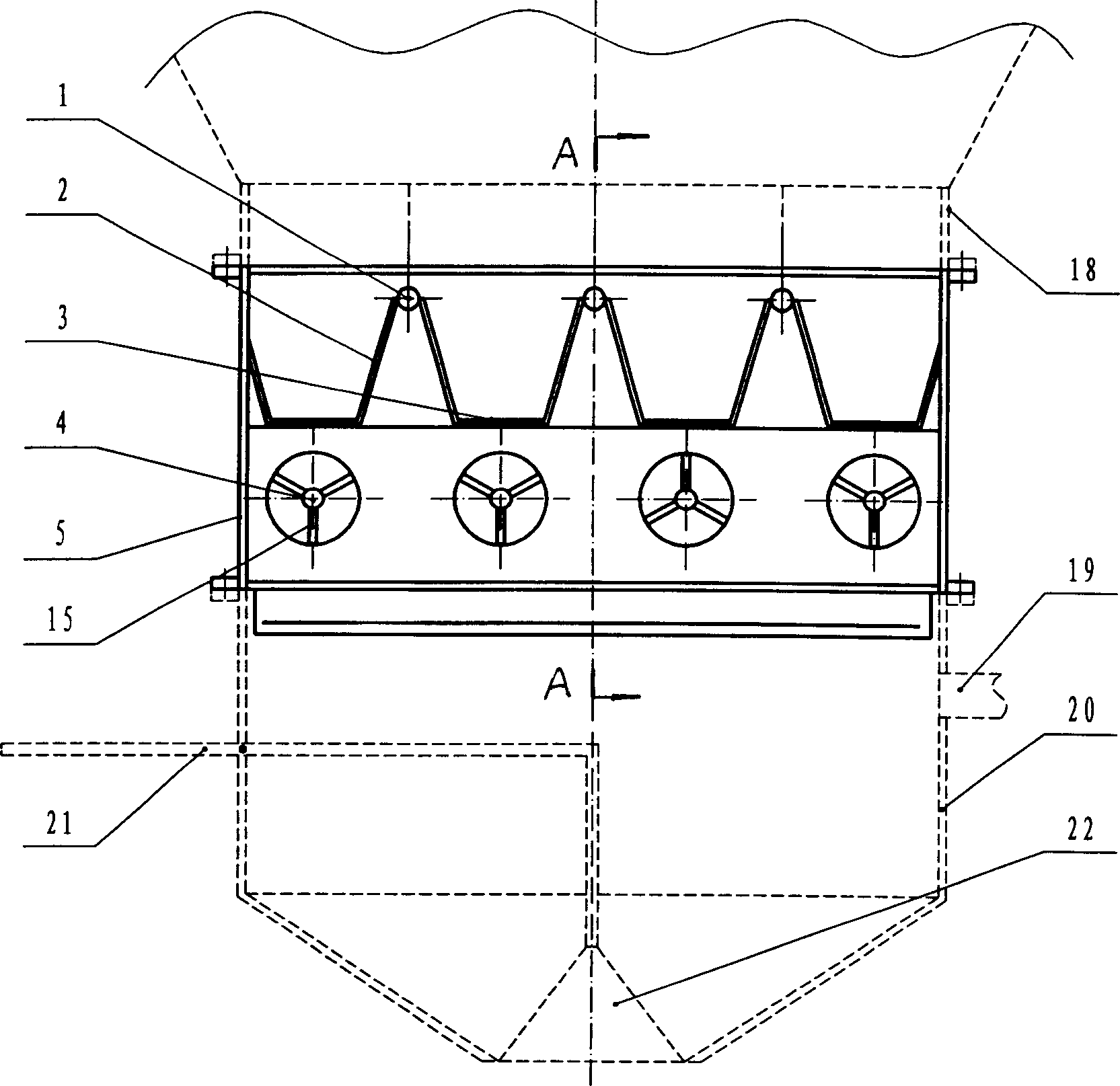
[0016] The embodiments of the present invention will be further described in conjunction with the accompanying drawings. This embodiment is used to illustrate the present invention, but not to limit the present invention in any way.

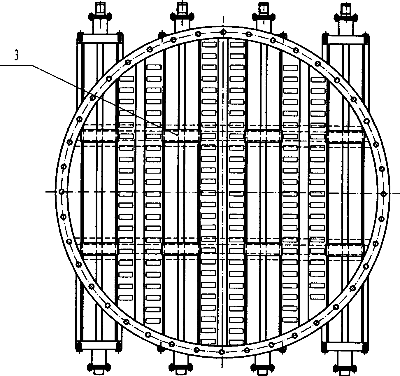
[0017] Swing-type industrial furnace discharge device, including the upper part connected with the furnace body 18, the lower part connected with the bell-shaped hopper 20 shell 5, the shell 5 is equipped with a combination of porous air distribution board 2, fixed distance partition 3 connected cloth The lower end of wind plate 2. At least one group of air distribution plates 2 is arranged in the shell 5, the cross section of the combination of air distribution plates 2 is inverted trapezoidal, and the upper ends of adjacent combined air distribution plates 2 are welded and fixedly connected by round steel 1. The number of spacer partitions 3 is at least two, and each spacer partition 3 is spaced apart from each other. The round steel 1 and the...


PUM


Abstract

This invention belongs to industry oven materials feeding device technique and to one swing industry feeding device, which Comprises one shell connected to oven on top and clock cover on down part, wherein, the shell inside is fixed with multi-hole distribution composition with certain distance connected to the distribution board down end; the distribution board composition part is located with swing structure; the swing structure comprises rotation axis and fin slices on it with rotation axis is fixed on the axis end supportive part of shell.

Description

technical field [0001] The invention belongs to the technical field of discharge devices for industrial furnaces, in particular to a swing-type discharge device for industrial furnaces. Background technique [0002] At present, the discharge device of industrial furnace, especially the discharge device of shaft kiln generally adopts pallet discharge machine, disc type discharge machine and so on. The pallet discharge machine discharges the material by pushing and pulling the pallet. During the discharge process, the air supply needs to be stopped. Although this kind of device is low in cost and easy to use, there are many problems: 1. Stop the air supply during the discharge process, making the furnace Oxygen supply is not uniform in the internal calcination, the temperature is unstable, and the calcination time increases, which affects the calcination effect and reduces the yield; 2. The push-pull process causes the system to be leaked, causing the dust generated by calcina...

Claims


Application Information

Patent Timeline
Patent Type & Authority Applications(China)
IPC IPC(8): F27D3/04
Inventor 马成锁李勇
Owner SHANXI KWONG FUK ENG
Why Eureka
Try Eureka