Supercharge Your Innovation With Domain-Expert AI Agents!

Variable focal lens

一种变焦透镜、透镜的技术,应用在变焦透镜领域,能够解决不会提供、不能确信使用者等问题

Active Publication Date: 2006-06-28
CORNING INC
View PDF2 Cites 22 Cited by
  • Summary
  • Abstract
  • Description
  • Claims
  • Application Information

AI Technical Summary

Problems solved by technology

In practice, however, lens manufacturers usually cannot influence the user to apply voltages to the hollow body electrodes, and therefore cannot be sure that the user will not supply a voltage higher than the threshold V 2 voltage

Method used


Image

  • Variable focal lens
  • Variable focal lens
  • Variable focal lens

Examples


Embodiment Construction

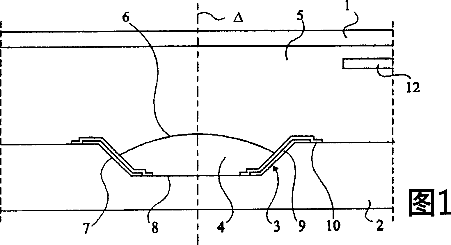
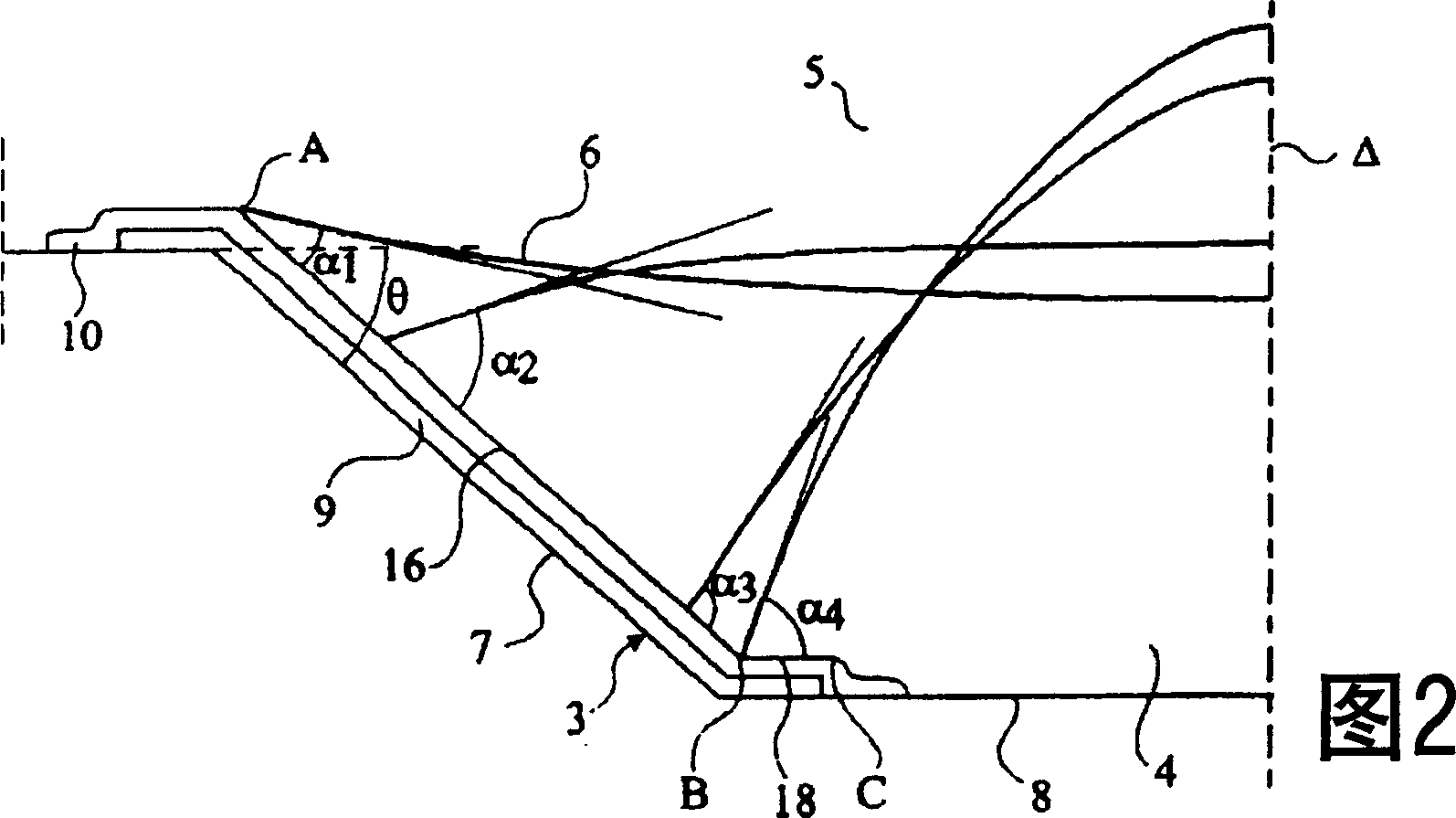
[0035]The invention consists in providing an intermediate surface between the conical surface 7 and the base 8 of the recess 3, wherein, in a plane containing the optical axis Δ of the lens, at the connection zone between the conical surface and the intermediate surface, perpendicular to the The angle between the plane of the optical axis and the tangent plane of this midplane is larger than the angle between the plane perpendicular to the optical axis and the cone, or the angle between the plane perpendicular to the optical axis Δ and the cone increases rapidly when moving away from the junction zone . The electrode 9 then extends over the conical surface 7 and the intermediate surface and, if necessary, over a part of the base 8 . The shape of the outer surface of the insulating layer 10 covering the electrode 9 replicates the shape of the notch 3 . As a result, the shell that moves the periphery of the deformable refractive surface 6 along its walls comprises: an upper par...


PUM


Abstract

The invention relates to a variable focal lens comprising a chamber containing a conductive liquid (5) and an insulating liquid (4) of different refractive indices, the surface of contact between the two liquids forming a deformable refractive surface (6) whose periphery is caused to move along the walls of a housing under the effect of an electric voltage (V). The housing comprises an upper portion (16) inclined relative to a plane perpendicular to the optical axis (”) of the lens, a lower portion (34, 48, 52) more inclined than the upper portion and a zone of junction (B') between the upper and lower portions, playing the role of a stop for the deformable refractive interface.

Description

technical field [0001] The present invention relates to a zoom lens, and more particularly, to a lens that deforms a liquid droplet using the electrowetting phenomenon and an optical device including the lens. Background technique [0002] Embodiments of a zoom lens are described in the applicant's European patent EP1166157. [0003] Figure 1 shows a cross-section of an exemplary conventional zoom lens along a plane containing the optical axis Δ of the lens. A cell is defined by two insulating transparent plates 1 and 2 and side walls not shown. The plates and the side walls define a sealed cavity filled with an insulating fluid and a conductive fluid which is immiscible with the insulating fluid and has the same density as it but a different refractive index. The lower plate 2 is not flat and includes a dimple or notch 3 for receiving a drop 4 of insulating liquid. The remaining hollow is filled with conductive liquid 5 . Typically, conductive fluids are aqueous liquids...

Claims


Application Information

Patent Timeline
Patent Type & Authority Applications(China)
IPC IPC(8): G02B3/14G02B7/04G03B30/00
CPCG02B3/14G02B26/005G02B3/12
Inventor 热罗姆·珀瑟
Owner CORNING INC
Features
  • R&D
  • Intellectual Property
  • Life Sciences
  • Materials
  • Tech Scout
  • Unparalleled Data Quality
  • Higher Quality Content
  • 60% Fewer Hallucinations
Learn More