
Light-emitting diode lamp of having synchronization pins, and lamp string of synchronous light-emitting diode

A light-emitting diode lamp, light-emitting diode technology, applied in the direction of light source, electric light source, electric lamp circuit layout, etc., can solve the problem of inability to obtain synchronization and so on

Inactive Publication Date: 2006-07-05
SEMISILICON TECH
View PDF0 Cites 1 Cited by
  • Summary
  • Abstract
  • Description
  • Claims
  • Application Information

AI Technical Summary

Problems solved by technology

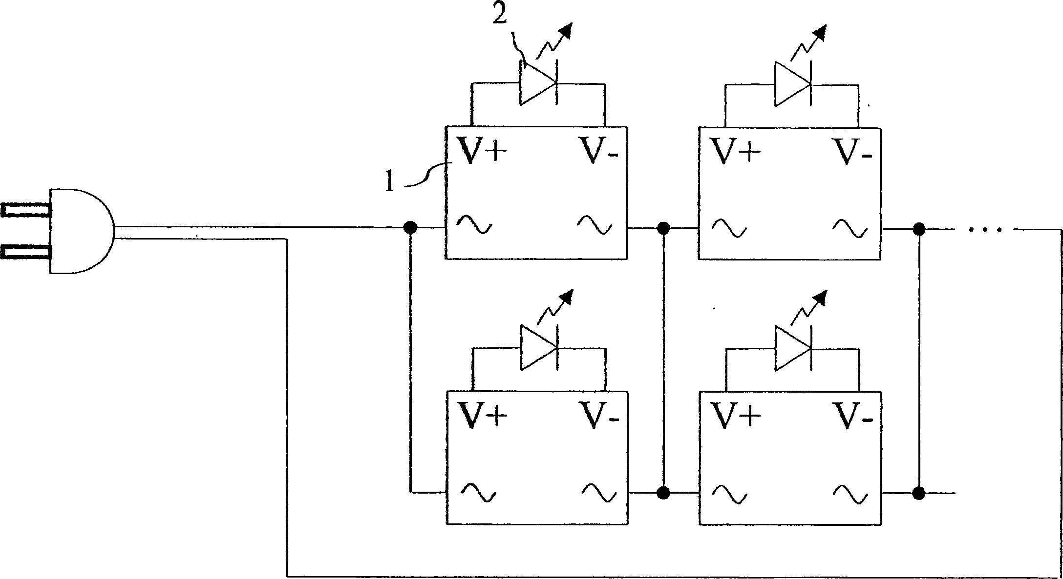
However, the disadvantage of the known LED light sets 2 is that they are respectively implanted with independent control ICs. Therefore, when applied to a light string, the color change of each LED light set 2 is an independent action after the power is turned on, and synchronization cannot be achieved.

Method used


Image

  • Light-emitting diode lamp of having synchronization pins, and lamp string of synchronous light-emitting diode
  • Light-emitting diode lamp of having synchronization pins, and lamp string of synchronous light-emitting diode
  • Light-emitting diode lamp of having synchronization pins, and lamp string of synchronous light-emitting diode

Examples


Embodiment Construction

[0029] While the invention will be fully described with reference to the accompanying drawings, which contain preferred embodiments of the invention, it should be understood before proceeding that those skilled in the art may modify the invention described herein while obtaining the full scope of the invention. effect. Therefore, it should be understood that the following description is a broad disclosure for those skilled in the art, and its content is not intended to limit the present invention.

[0030] Please refer to FIG. 5 , which is a circuit block diagram showing the LED lamp set of the present invention. The present invention provides an RGB light emitting diode lamp set 10, comprising a red light emitting diode (RLED) 11, a green light emitting diode (GLED) 12, a blue light emitting diode (BLED) 13 and a control circuit 14, the control circuit can be controlled by An integrated circuit is implemented, and the control circuit 14 has been programmed to drive the color...


PUM


Abstract

The light emitting diode includes at least one light emitting diode and a control circuit. The light emitting diode lamp has an anode pin, a cathode pin and a synchronizing pin. The anode pin and the cathode pin are used to receive a DC voltage. The synchronizing pin is connected to the control circuit. The synchronizing light emitting lamp string consists of even numbers of light emitting lamps and at least one power converter. Each light emitting diode lamp has a synchronizing pin. All the synchronizing pins are connected together. The control circuit above changes the color of diode by controlling a reference signal on the synchronizing pin.

Description

technical field [0001] The invention relates to a light-emitting device, in particular to an RGB light-emitting diode lamp group and a synchronous light-emitting diode lamp string with synchronous signals. Background technique [0002] The application of light strings has always been very wide, such as Christmas light strings, landscape light strings, building light strings, etc. With the progress of light-emitting diode (LED) manufacturing process and the cheaper price, it is also a good idea to apply LEDs to light strings. This is a new trend, but because LEDs are basically suitable for DC power supply, and light strings are used in the environment of AC power supply, how to apply LEDs to light strings, some products have been seen in the market. But how to achieve synchronous change is an obstacle to be overcome. The present invention has made an in-depth research on this subject, and has obtained concrete results, so an application for a patent is proposed. [0003] Th...

Claims


Application Information

Patent Timeline
Patent Type & Authority Applications(China)
IPC IPC(8): H05B37/00H05B37/02
Inventor 彭文琦
Owner SEMISILICON TECH
Learn More