Log splitter

A wood splitter and wood splitting wedge technology, applied in the field of wood splitters, can solve problems such as instability

Inactive Publication Date: 2006-07-12
TECHTRONIC OUTDOOR PRODS TECH
View PDF0 Cites 7 Cited by
  • Summary
  • Abstract
  • Description
  • Claims
  • Application Information

AI Technical Summary

Problems solved by technology

Therefore, regular log

Method used


Image

  • Log splitter
  • Log splitter
  • Log splitter

Examples


Embodiment Construction

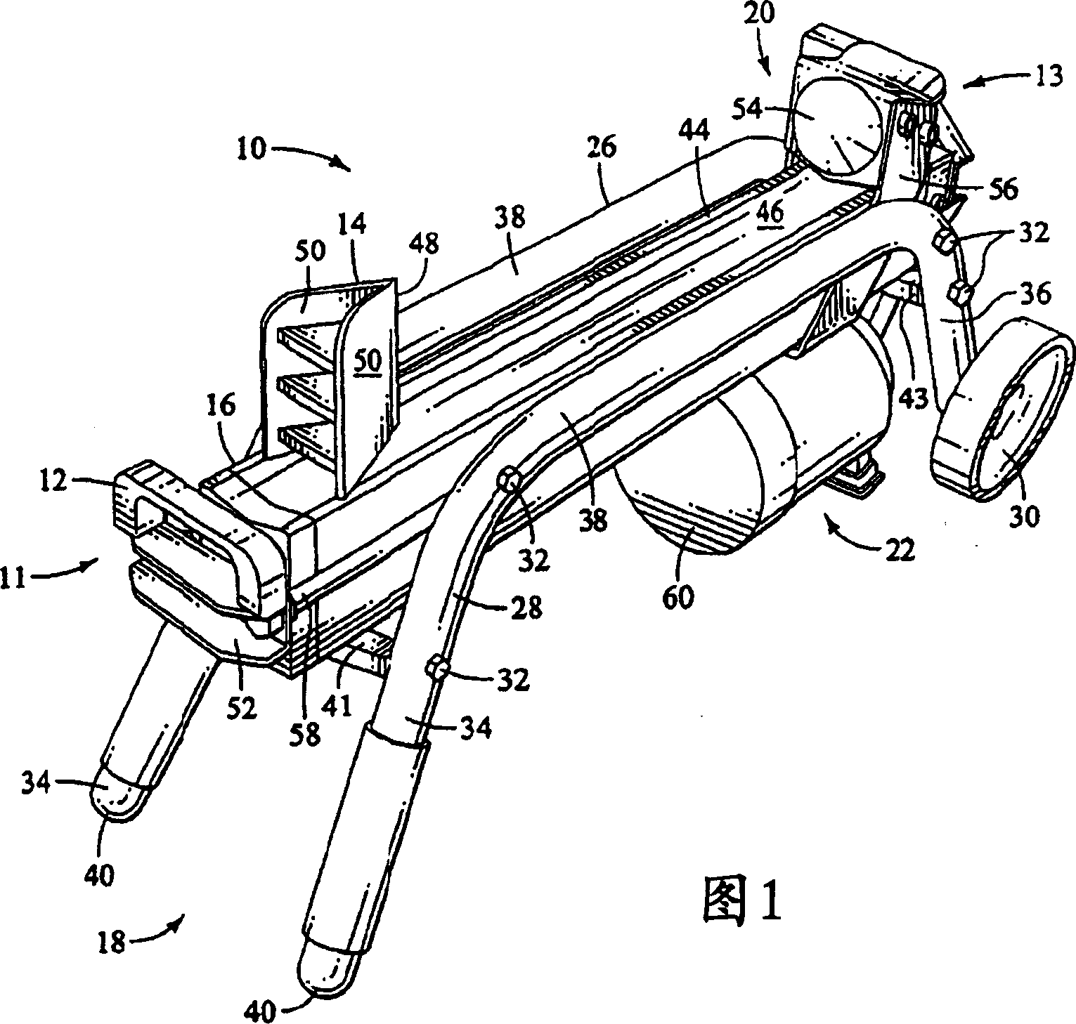
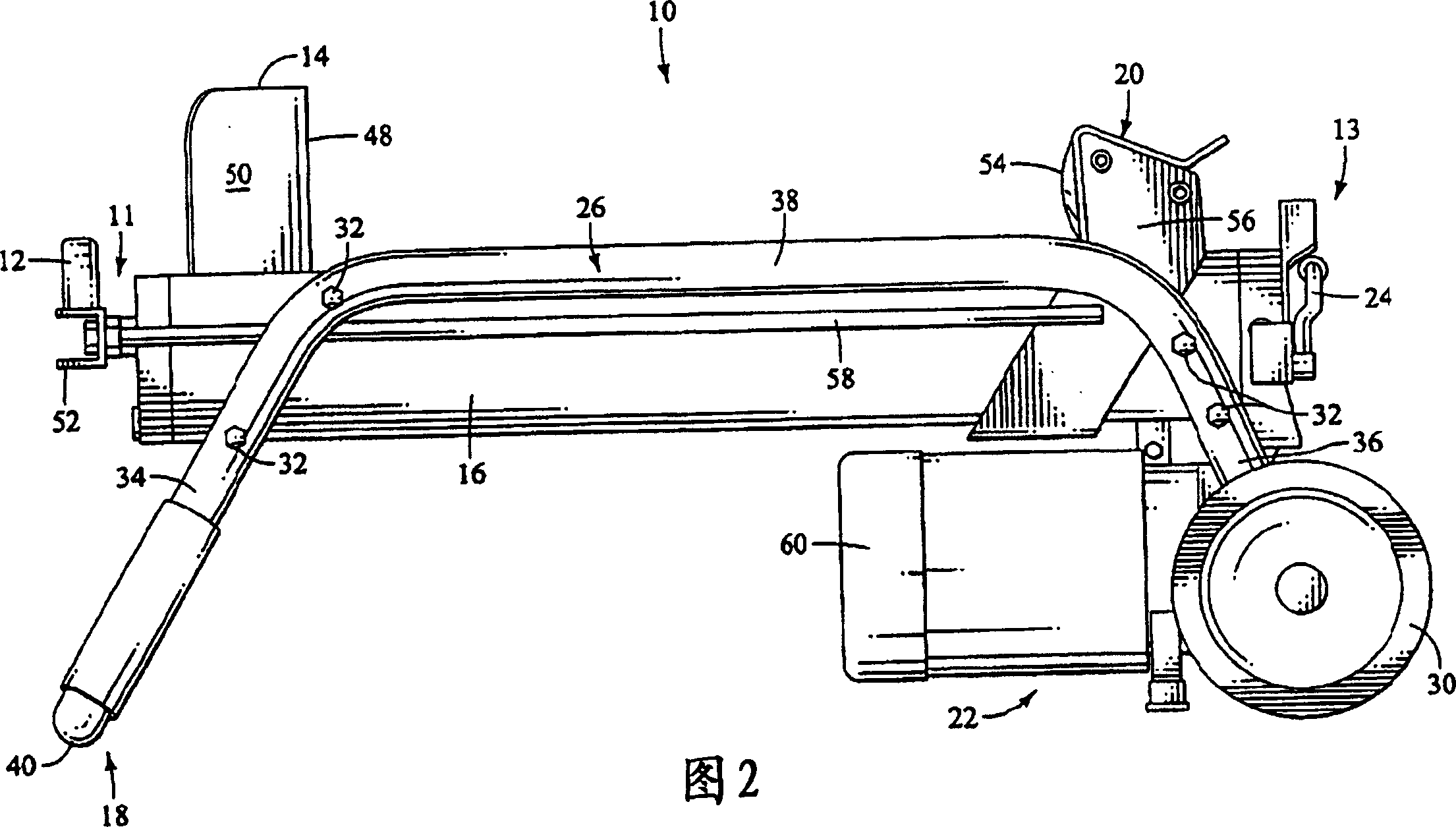
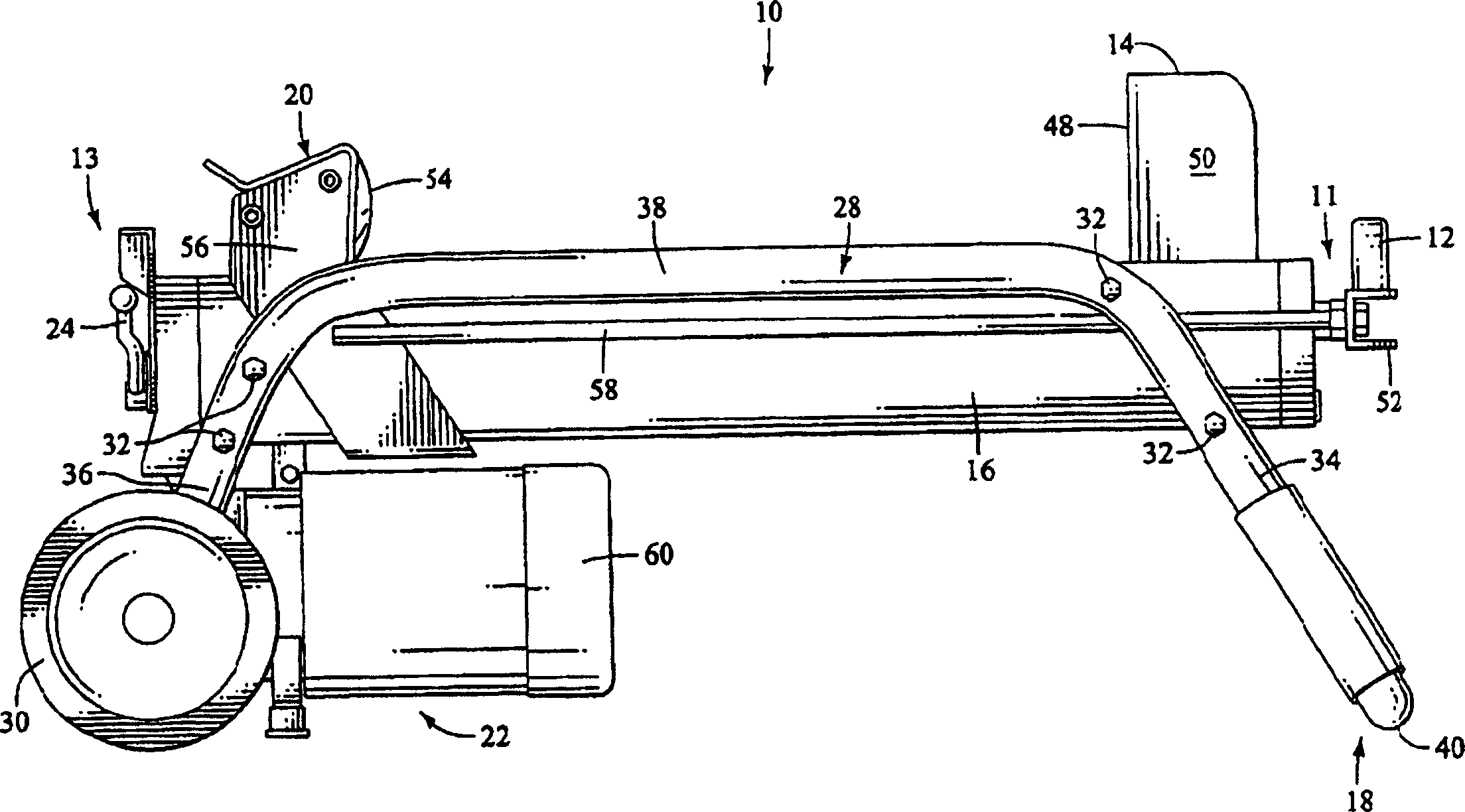
[0018] One embodiment of a log splitter 10 of the present invention is shown in Figures 1-2. The log splitter 10 includes a handle 12 , a splitting wedge 14 , a support 16 , a frame 18 , a guide assembly 20 , a control assembly 22 and a switch 24 . Preferably, the handle 12 is located at the front end 11 of the log splitter 10 and the switch 24 is located at the rear end 13 of the log splitter 10 so that the switch 24 is located near the control assembly 22 . The handle 12 is preferably located at the end opposite the switch 24 and control assembly 22 to make the log splitter 10 easier to move by allowing the user to lift the lighter end of the log splitter 10 .

[0019] In the preferred embodiment, as shown in FIGS. 1-2, the frame 18 includes a first side member 26, a second side member 28 and wheels 30 secured to each side member 26,28. The side members 26, 28 form a base for the log splitter 10 so that the log splitter 10 remains stable during transport and operation. The...


PUM


Abstract

A portably log splitter is provided. The log splitter comprises a base having a pair of one-piece side members , and a support member to which the one-piece side members are attached. The support member and the one-piece side members form a seat that is adapted to receive a log. The log splitter also includes a splitting wedge that is attached to the support member and a contact member that is configured to translate in a reciprocal manner adjacent to the support member in order to move the log. The log splitter also includes a control assembly operated by a switch to actuate the contact member in the reciprocal manner.

Description

technical field [0001] The present invention relates generally to a log splitter, and more particularly to a portable log splitter. Background technique [0002] Conventional log splitters are used to split large logs into smaller lumber that are more suitable for handling. Typically, these splitting devices employ a hydraulic system to split the log by moving a splitting wedge towards the log or by moving the log towards a stationary splitting wedge. These hydraulic systems are often very cumbersome, thereby rendering the log splitting device bulky and inconvenient when attempting to move the log splitting device between locations. Although typical devices that allow the portability of the log splitter are directly attached to the structural frame, these typically portable devices provide poor structural support systems for the log splitter. [0003] Large logs are very heavy and often have odd shapes, making it difficult to balance the log on a conventional log splitting...

Claims


Application Information

Patent Timeline
IPC IPC(8): B27L7/06
CPCB27L7/00B27L7/06
Inventor 克里斯·J·刘易斯塔库·欧西查理斯·K·朗肯尼思·M·布拉泽尔马里恩·雷诺兹
Owner TECHTRONIC OUTDOOR PRODS TECH
Why Eureka
Try Eureka