Refrigerator

A technology for refrigerators and cabinets, which is applied to lighting and heating equipment, cooling fluid circulation devices, household appliances, etc., and can solve problems such as conflicts between defrosting and cooling, energy consumption reduction for evaporator defrosting, and heating power loss. Achieve the effect of reducing refrigeration operation loss, stable defrosting work, and maintaining freshness

Inactive Publication Date: 2006-07-12
边雁
View PDF3 Cites 9 Cited by
  • Summary
  • Abstract
  • Description
  • Claims
  • Application Information

AI Technical Summary

Problems solved by technology

[0013] First, the separation plate separating the two evaporators only partially separates the two evaporators, but does not separate the two evaporators into two completely independent and closed space structures. There will be exchange of cold and hot heat, so the two evaporators will affect each other: one is that the evaporator in the defrosting state may not defrost completely and uncertainly, and the other is that the evaporator in the cooling state needs to produce more more cold energy to compensate for the loss of cold energy caused by the defrosting heating of the other evaporator
[0014] Second, since the defrosting of the evaporator still requires a defrosting heater, this will inevitably lead to a loss of heating power. On the other hand, the heating of the defrosting heater will consume additional cold energy stored in the frost layer of the evaporator
[0017] First: the frost layer of the evaporator must rely on the heat of the heater to be removed
[0018] Second: There must be cold and hot heat exchange between two or more evaporators, and the two evaporators will affect each other: one is that the evaporator in the defrosting state may not be completely defrosted, and the other is uncertain. The evaporator in the cooling state needs to generate more cold energy to compensate for the loss of cold energy caused by the defrosting heating of the other evaporator
There are still many patented technologies that use the relatively high temperature cold air circulation in the refrigerator to melt the frosting of the evaporator, but until now, there is still no existing technology that can really completely solve the energy consumption of the evaporator defrosting The problem of reducing the energy consumption of defrosting, and the conflict between defrosting and refrigeration caused by the reduction of energy consumption of evaporator defrosting - and this is exactly what the present invention strives to break through

Method used


Image

  • Refrigerator
  • Refrigerator
  • Refrigerator

Examples


Embodiment Construction

[0050] The present invention will be described in detail below in conjunction with the accompanying drawings.

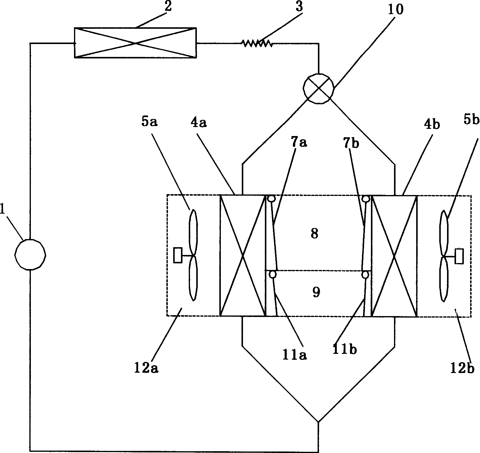
[0051] figure 2 It is a schematic flow chart of the refrigerator refrigeration cycle of the present invention. For simplicity and clarity, the present invention will be described in detail using a refrigerator having a refrigerating compartment and a freezing compartment.

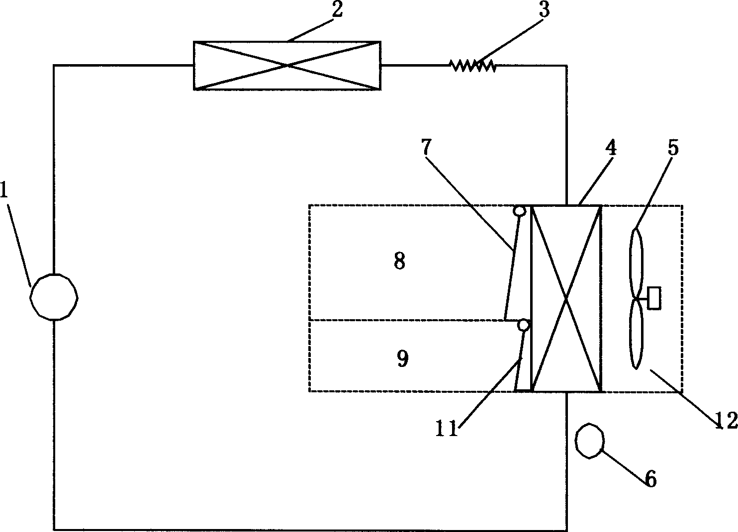
[0052] Such as figure 2 As shown, the refrigerant is driven by the compressor 1 and flows through the condenser 2 and the capillary tube 3. The output end of the capillary tube 3 is connected to the input port of the solenoid valve 10 to control the flow of the refrigerant from the two output ports of the solenoid valve 10. The evaporator 4a and the evaporator 4b, the refrigerant flows into the compressor 1 from the combination of the output ends of the evaporator 4a and the evaporator 4b, the above constitutes the refrigeration cycle of the refrigerator of the present invention.

[0053] Whe...


PUM


Abstract

The invention discloses a refrigerator, which arranges a heat separation wall inside the air-conditioning channel between the cooling room and the refrigerator box; therefore, the former one air-conditioning channel is divided into two independent sealing air-conditioning channels, while each channel has an evaporator, several wind gates through with different cooling rooms, and a fan for forced cooled air circulation. The invention can effectively utilizes the cooling energy stored by the frost layer of evaporator, and utilize the air in higher temperature of cooling room to de-frost of evaporator without any other heat resource, while the de-frost and the refrigeration are not conflicted. The invention can apply variable refrigerators.

Description

technical field [0001] The invention relates to a refrigerator. Background technique [0002] Existing, the most widely used is vapor compression refrigeration cycle refrigerator. [0003] According to different cooling methods, refrigerators can be divided into direct cooling refrigerators, indirect cooling refrigerators, and direct cooling and indirect cooling combined refrigerators. [0004] Direct cooling refrigerators, also known as frost refrigerators, are named because the evaporator directly absorbs the heat of food for cooling. The evaporator in the cooling chamber of direct cooling refrigerators is prone to frosting, and defrosting is more troublesome. [0005] Indirect cooling refrigerators, also known as frost-free refrigerators, rely on the fan in the refrigerator to force air convection circulation to exchange heat with the evaporator to achieve indirect cooling of stored food. The intercooled refrigerator has a finned tube eva...

Claims


Application Information

Patent Timeline
Patent Type & Authority Applications(China)
IPC IPC(8): F25D17/08
Inventor 边雁
Owner 边雁
Why Eureka
Try Eureka