Adjustable lifting support apparatus

A supporting device and adjustable technology, applied in the direction of identification devices, instrument parts, instruments, etc., can solve problems such as inability to adjust, inconvenience, and fatigue of spring elasticity, and achieve the effects of simple structure, avoidance of functional failure, and cost reduction.

Inactive Publication Date: 2006-07-19
BENQ CORP
View PDF0 Cites 5 Cited by
  • Summary
  • Abstract
  • Description
  • Claims
  • Application Information

AI Technical Summary

Problems solved by technology

Since the torsional force of the springs of the lifting device is fixed and cannot be adjusted, it is extremely inconvenient for different users
And, after a long time of use, the sp

Method used


Image

  • Adjustable lifting support apparatus
  • Adjustable lifting support apparatus
  • Adjustable lifting support apparatus

Examples


Example Embodiment

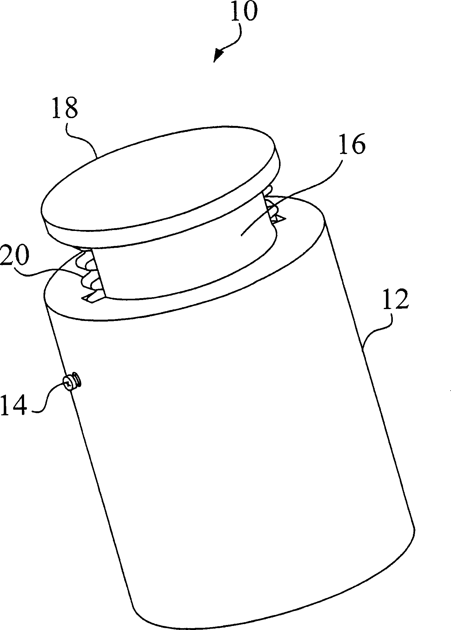
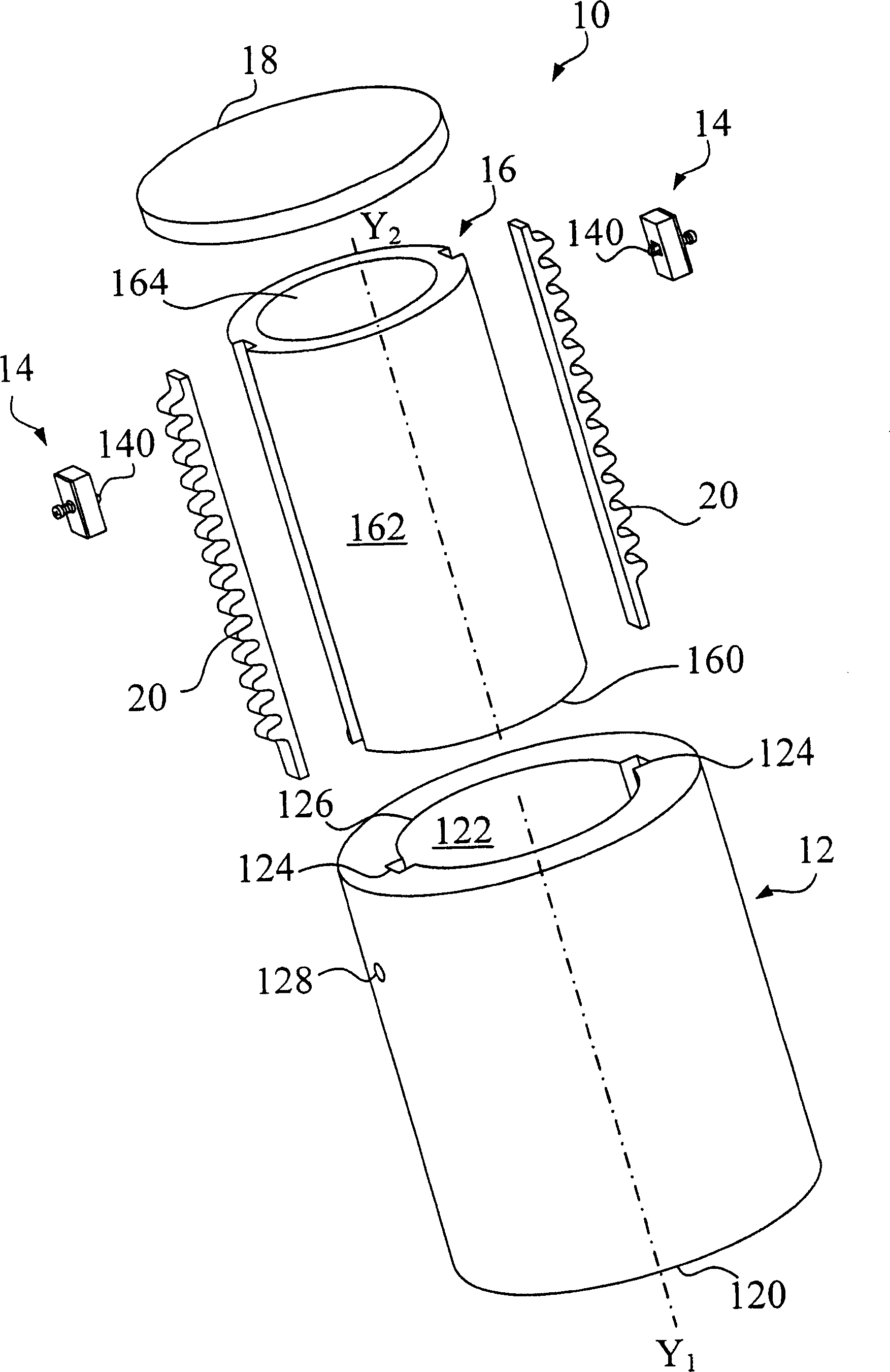
[0017] see figure 1 as well as figure 2 , figure 1 It is an external view of the adjustable lifting support device 10 of the present invention. figure 2 for figure 1 An exploded view of the middle adjustable lifting support device 10. The adjustable lifting support apparatus (Adjustable lift support apparatus) 10 includes a base (Base) (not shown), a sleeve (Sleeve) 12, at least one meshing element (Meshing device) 14, a shaft rod (Shaft) 16 and a Support frame (Support)18. In practical application, both the sleeve 12 and the shaft 16 can be substantially designed to be columnar (Pillared) or arc (Arc). In this embodiment, the sleeve 12 and the shaft 16 are cylindrical, and the adjustable lifting support device 10 includes two engaging elements 14 .

[0018] like figure 2 As shown, the sleeve 12 is mounted on a base (not shown) via a tail end 120 thereof, and the sleeve 12 has a first axis Y 1 and an inner surface 122 . At least one groove (Groove) 124 opens from a...


PUM


Abstract

The invention relates to an adjustable lifting shore device which comprises a base, a cylinder, at least one contacting unit, an axle rod and a supporting frame. The cylinder is fixed on the base. At least one groove is formed on an inner surface of the cylinder along the first axle. Each contacting unit is corresponding with one of the grooves and comprises a flexure overhang member locating to the first axle direction. One end of the axle rod is inserted into the cylinder. It provides at least one dental plate on an external surface of the axle rod along to the second axle direction. The up and down of the supporting frame fixed on the axle rod forces a force on the supporting frame, so that each dental plate and the flexure overhang member of the corresponding contact unit can do relative movement to adjust the height of the supporting frame.

Description

technical field [0001] The present invention relates to an adjustable lifting support apparatus (Adjustable lift support apparatus), in particular to an adjustable lift support apparatus which can avoid function failure due to long-term use. Background technique [0002] Recently, flat panel displays have become more and more popular, and have gradually replaced projection devices and cathode ray tube displays (Cathode ray tube displays, CRT displays). A flat panel display, such as a liquid crystal display (LCD), is usually installed on a lifting device so that it can be raised or lowered. [0003] In actual use, it is desirable to be able to adjust the height of the flat-panel display to the most suitable viewing position. At present, there are various existing technologies about the lifting device being used, such as a mechanism using a ball slide rail with a constant force spring, a mechanism using a connecting rod with a spring, or other similar mechanisms. Since the t...

Claims


Application Information

Patent Timeline
IPC IPC(8): G12B9/08G09F9/00
Inventor 许维新
Owner BENQ CORP
Why Eureka
Try Eureka