Manufacturing method of shielding case bracket

A manufacturing method and shielding cover technology are applied in the field of manufacturing shielding cover brackets, which can solve the problems of upward burrs on flange edges, top damage to PCB wiring layers, etc.

Inactive Publication Date: 2020-09-01
SHANGHAI CHUANGGONG COMM TECH
View PDF5 Cites 3 Cited by
  • Summary
  • Abstract
  • Description
  • Claims
  • Application Information

AI Technical Summary

Problems solved by technology

[0006] The technical problem to be solved by the present invention is to provide a manufacturing method of the shielding cover bracket in order to overcome the defect that upward burrs are easily generated on the flange edge of the shielding cover bracket in the prior art, causing damage to the PCB wiring layer

Method used


Image

  • Manufacturing method of shielding case bracket
  • Manufacturing method of shielding case bracket
  • Manufacturing method of shielding case bracket

Examples


Embodiment Construction

[0042] The present invention is further illustrated below by means of examples, but the present invention is not limited thereto within the scope of examples.

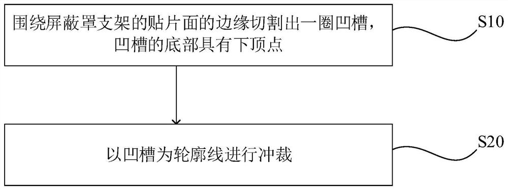
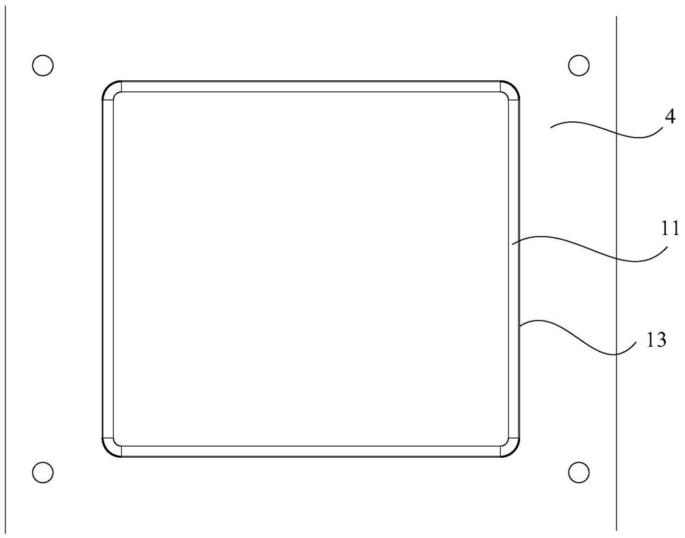
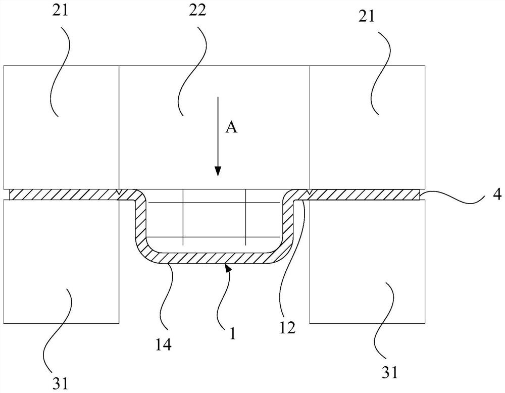
[0043] This embodiment discloses a manufacturing method of the shield bracket 1, such as Figure 1-4 As shown, the manufacturing method of the shield bracket 1 includes steps: S10, cutting a circle of grooves 13 around the edge of the patch surface 11 of the shield bracket 1, the bottom of the groove 13 has a lower apex 131; S20, using the groove 13 Punching for outline.

[0044] In this embodiment, since the groove 13 is added on the edge of the patch surface 11, when the upper die punch 22 punches down the raw material 4 of the shield bracket 1, the raw material 4 of the shield bracket 1 will not pass through the The three stages from elastic deformation to plastic deformation and then to fracture and separation, but the following apex 131 is the tear point directly fracture and separation, so as to avoid the burr p...


PUM


Abstract

The invention discloses a manufacturing method of a shielding case bracket. The manufacturing method comprises the following steps of S10, cutting a circle of groove around the edge of a patch surfaceof the shielding case bracket, the bottom of the groove being provided with a lower vertex; and S20, blanking with the groove as the contour line. Due to the fact that the groove is additionally formed in the edge of the patch surface, when an upper die punch downwards punches raw materials of the shielding case bracket, the raw materials of the shielding case bracket are directly fractured and separated with the lower vertex as a tearing point, and therefore the burr problem caused by deformation dislocation and re-fracture is avoided. According to the manufacturing method, burrs on the surface of the flange edge patch are eliminated, and function failure caused by piercing of PCB wiring by the burrs is avoided; procedures of electrolysis or chemical treatment and the like for removing burrs in the later period of manufacturing the shielding case bracket are omitted; and in addition, burrs cannot be generated even if the die is abraded in the later period, and the service life of thedie is prolonged.

Description

technical field [0001] The invention relates to the field of intelligent communication equipment manufacturing, in particular to a method for manufacturing a shield bracket. Background technique [0002] At present, in order to ensure that the signals and functions of each module are independent of each other and not interfered by other modules, communication products will take shielding measures during the design process, and shielding with a shield is the most commonly used method. The shielding cover is usually two-piece, one is a frame, which is used for patching; the other is a cover, which is located above the frame and is used to fit together with the frame. Among them, the bracket adopts a stretched form, and the cover adopts a bending process. This form of shielding cover can be repaired and has good sealing performance. [0003] For the manufacturing process of the shield bracket, the outer periphery of the upper side of the bracket has a flange edge, and the side...

Claims


Application Information

Patent Timeline
Patent Type & Authority Applications(China)
IPC IPC(8): B21D35/00B21D28/02B21D28/14
CPCB21D35/002B21D28/02B21D28/14
Inventor 罗振宇曾凡杰
Owner SHANGHAI CHUANGGONG COMM TECH
Why Eureka
Try Eureka