Printer

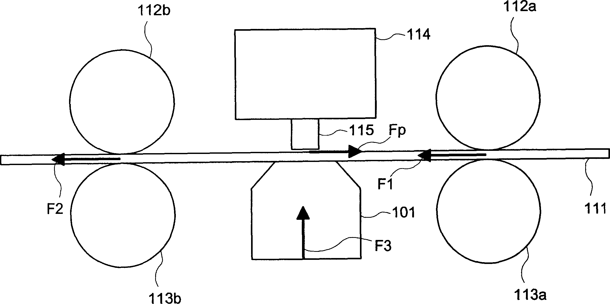
A technology of printers and print heads, applied in printing devices, printing, transfer materials, etc., can solve the problem of not being able to reduce the force of F3

Inactive Publication Date: 2006-07-26
OKI ELECTRIC IND CO LTD
View PDF1 Cites 11 Cited by
  • Summary
  • Abstract
  • Description
  • Claims
  • Application Information

AI Technical Summary

Problems solved by technology

Therefore, it is not poss

Method used


Image

  • Printer
  • Printer
  • Printer

Examples


Embodiment Construction

[0031] Hereinafter, embodiments of the present invention will be described in detail with reference to the drawings.

[0032] Figure 4 is a schematic diagram of the printer in the embodiment of the present invention.

[0033] In the figure, 10 is a printer, which is provided with: a print medium insertion port 11 for inserting a print medium 18, a print medium conveying path 12 for conveying the print medium 18, and several conveying rollers configured along the print medium conveying path 12 13 and pressure roller 14, the printing head 15 arranged on the printing section 20 in the middle of the above-mentioned printing medium transport path 12, the guide 16 installed on the carriage (carriage) (not shown) of the printing head 15, And the printing platen 17 arranged on the printing unit 20 . Here, the above-mentioned printer 10 is a voucher accounting machine or the like used in financial institutions such as banks, post offices, and credit unions (financial cooperatives in...


PUM


Abstract

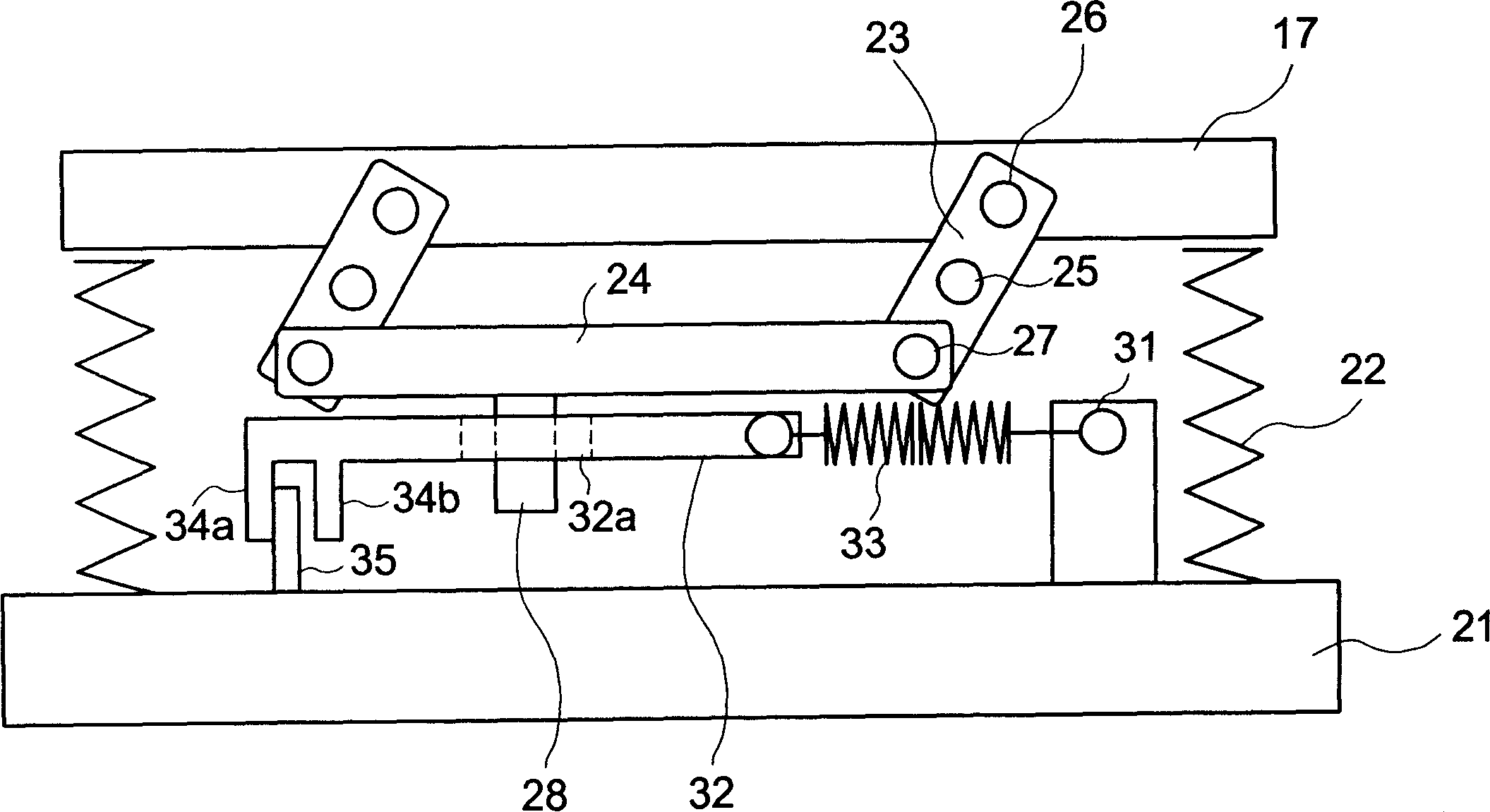
A printer has a platen which vertically moves with respect to a printing head to press a medium against a guide member from below. In this printer, the platen is attached to a support member through a spring member to be urged upward by the spring member, and the arrangement is such that when the thickness of the medium is more than a predetermined value, the platen is further urged upward by a spring force reinforcing mechanism, whereby the force with which the platen presses the medium can be suitably controlled according to the thickness of the medium, so that printing can be performed in a stabilized manner.

Description

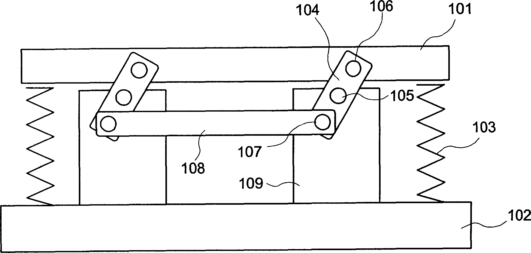
technical field [0001] The present invention relates to the invention of a printer. Background technique [0002] In the past, in financial institutions such as banks, post offices, and credit banks (financial cooperatives in Japan), printers such as voucher bookkeeping machines have been used to record accounts on vouchers such as deposit books (for example, refer to Patent Document 1). In order to print the voucher at a predetermined position of the voucher as a printing medium, in this printer, the voucher inserted into the voucher accounting machine from the insertion port is conveyed to the printing part by a conveying roller or the like provided on the conveying path. . The printing section is provided with a print head, a printing platen (platen) opposite to the above-mentioned print head across the conveying path, and a guide for guiding the upper surface of the fold, and the guide is installed on the print head . Once the voucher has reached the print section, th...

Claims


Application Information

Patent Timeline
IPC IPC(8): B41J11/14B41J11/20
CPCB41J11/20B41J11/14B41J25/308
Inventor 箭野达也久下英七池田恭之
Owner OKI ELECTRIC IND CO LTD
Why Eureka
Try Eureka