Temperature sensor

A temperature sensor and sensor technology, applied in the direction of thermometers, thermometer parts, instruments, etc., can solve problems such as hindering parts and hindering the simplification of manufacturing processes, and achieve the effect of reducing the number of parts

Active Publication Date: 2006-07-26
TDK CORPARATION
View PDF5 Cites 24 Cited by
  • Summary
  • Abstract
  • Description
  • Claims
  • Application Information

AI Technical Summary

Benefits of technology

This patented technology makes it possible for an improved type of temperature sensing device that has fewer components than previous designs.

Problems solved by technology

Technological Problem addressed in this patented technology describes conventional temperatures detectors used in electronic devices due to their use of multiple parts including an inner case containing a heat sensitive material called PTC or resistance type temperature detector(s). These parts have been separately placed during production, making assembly processes complicated.

Method used


Image

  • Temperature sensor
  • Temperature sensor
  • Temperature sensor

Examples


Embodiment Construction

[0046] Hereinafter, preferred embodiments of the temperature sensor of the present invention will be described in detail with reference to the drawings. In addition, the same symbols are used for the same or identical parts, and repeated explanations are omitted.

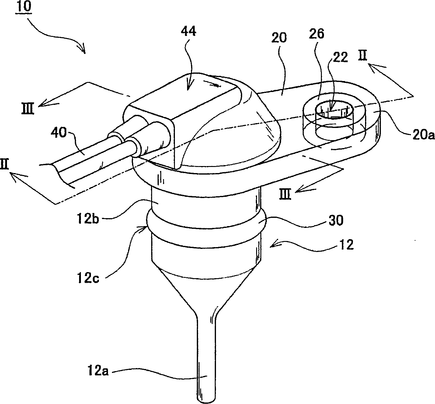
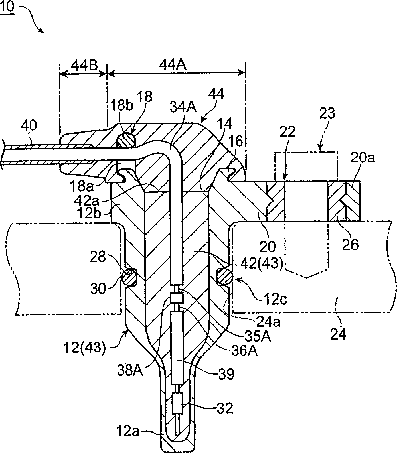
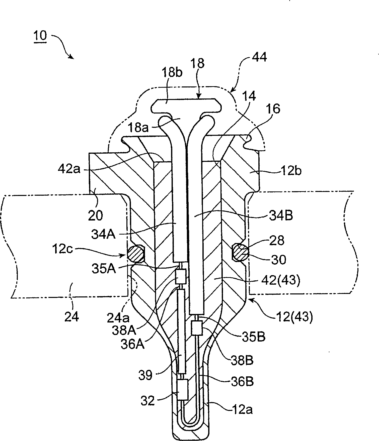
[0047] figure 1 A schematic perspective view showing a temperature sensor according to an embodiment of the present invention. figure 2 yes figure 1 Line II-II sectional view of the temperature sensor shown. image 3 yes figure 1 Line III-III sectional view of the temperature sensor shown.

[0048] Figure 1 ~ Figure 3 The shown temperature sensor 10 according to the embodiment of the present invention is inserted into an automatic transmission (Automatic Transmission) of an automobile, and detects the temperature of the ATF in the transmission. The temperature sensor 10 has a bottomed cylindrical holder 12 made of polyphenylene sulfide (PPS) resin. Since this PPS resin has high fluidity, a high-precision...


PUM


Abstract

The present invention provides a temperature sensor with a reduced number of parts. In a temperature sensor (10), an entire opening portion (14) of a holder (12) is covered by a cap portion (44A) of a sensor cover (44), so that water drops etc. are prevented from entering between the holder (12) and a filled resin portion (42). Further, wire breakage in a harness pair (34A, 34B) caused by excessive bending is restricted by a neck portion (44B) of the sensor cover (44). The cap portion (44A) and the neck portion (44B) are both part of the sensor cover (44) and are integrated together. In the temperature sensor (10) with such a sensor cover (44), the number of parts is less than that of a temperature sensor (50) where a cap and a lead-wire lead-out member are separate bodies.

Description


Claims


Application Information

Patent Timeline
Owner TDK CORPARATION
Why Eureka
Try Eureka