
Vertical injection molding machine

A technology for injection molding and molding machines, which is applied in the field of vertical injection molding machines, can solve the problems of drive system damage, cost increase, labor and time extension, and achieve the effect of improving production efficiency

Inactive Publication Date: 2006-08-16
TOYO MACH & METAL CO LTD
View PDF1 Cites 1 Cited by
  • Summary
  • Abstract
  • Description
  • Claims
  • Application Information

AI Technical Summary

Problems solved by technology

[0005] but, Image 6 In the above-mentioned vertical injection molding machine, since the stop pin is repeatedly pressed against the stop body by the number of times of molding by the forward and reverse rotation of the turntable, the contact parts of the stop pin and the stop body are worn, respectively. If the vertical forming machine is operated for a long time, it will be difficult to stop the lower molds at the specified positions due to the wear of the positioning stop pins and other parts, and the molds may be damaged when the molds are closed depending on the situation.
In addition, since it is necessary to periodically replace wearing parts such as stopper pins and stoppers, labor and time are extended in the replacement of wearing parts, and the start-up of each molding machine must be interrupted for the parts replacement work. , and furthermore, in a vertical injection molding machine in which insert parts such as metal and resin are integrally molded, the manufacturing cost of the manufactured molded body becomes high
[0006] In addition, if the stop pin and the stop body collide, not only the stop pin and the stop body, but also the drive system of the turntable may be damaged.
Therefore, since it is necessary to surely stop the turntable just before the stopper pin abuts against the stopper, there is a problem that the deceleration distance before stopping needs to be kept large, and if the deceleration distance is kept long, the turntable will start to move from the rotation of the turntable. It takes longer to stop and as a result the overall forming cycle takes longer
Also, like in Image 6 As in the shown two-station vertical injection molding machine in which two molds are mounted on the turntable, the two molds on the turntable are repeatedly rotated back and forth every 180° according to the rotation of the turntable. The stopper pin comes into contact with the stopper fixed on the base, etc. to stop the lower mold at a predetermined position. Since it rotates in the same direction every 120°, a complex structure and control for contacting the stopper is required, resulting in a decrease in reliability and an increase in cost
[0007] In addition, in Image 6 Among them, the turntable is stopped by pressing the stopper pin against the stopper body. If this structure is not used, but the rotating turntable is stopped only by the control of the servo motor as its driving source, not only the turntable cannot be The stop position of the turntable stops within a given range, and there will be a phenomenon that the stop position has a large deviation with the passage of the start time of the turntable.

Method used


Image

  • Vertical injection molding machine
  • Vertical injection molding machine
  • Vertical injection molding machine

Examples


Embodiment Construction

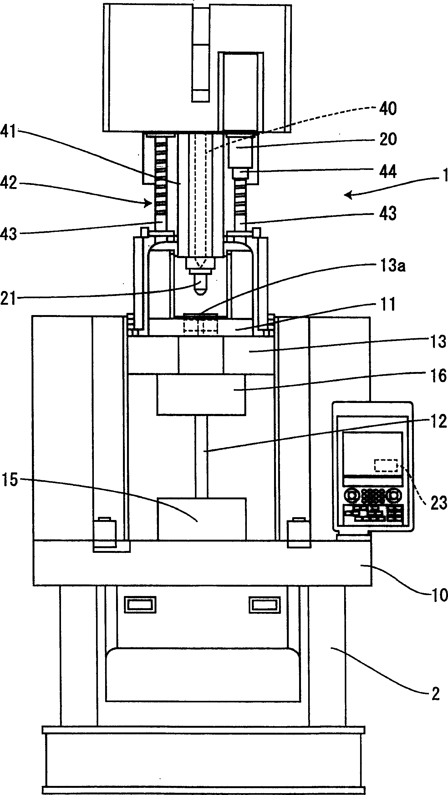
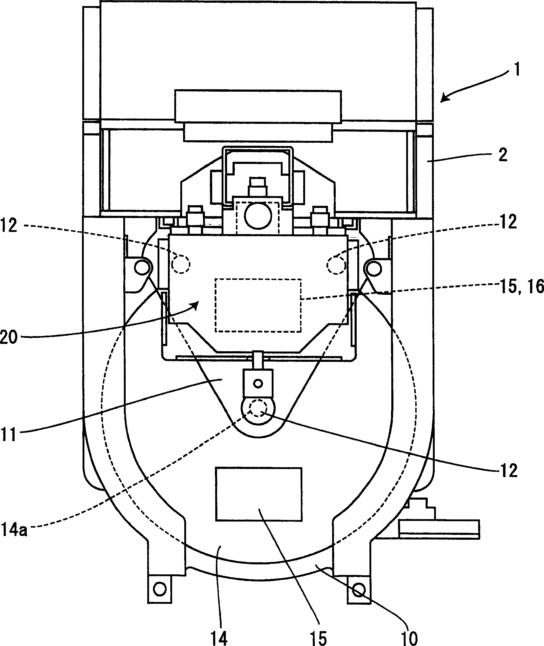
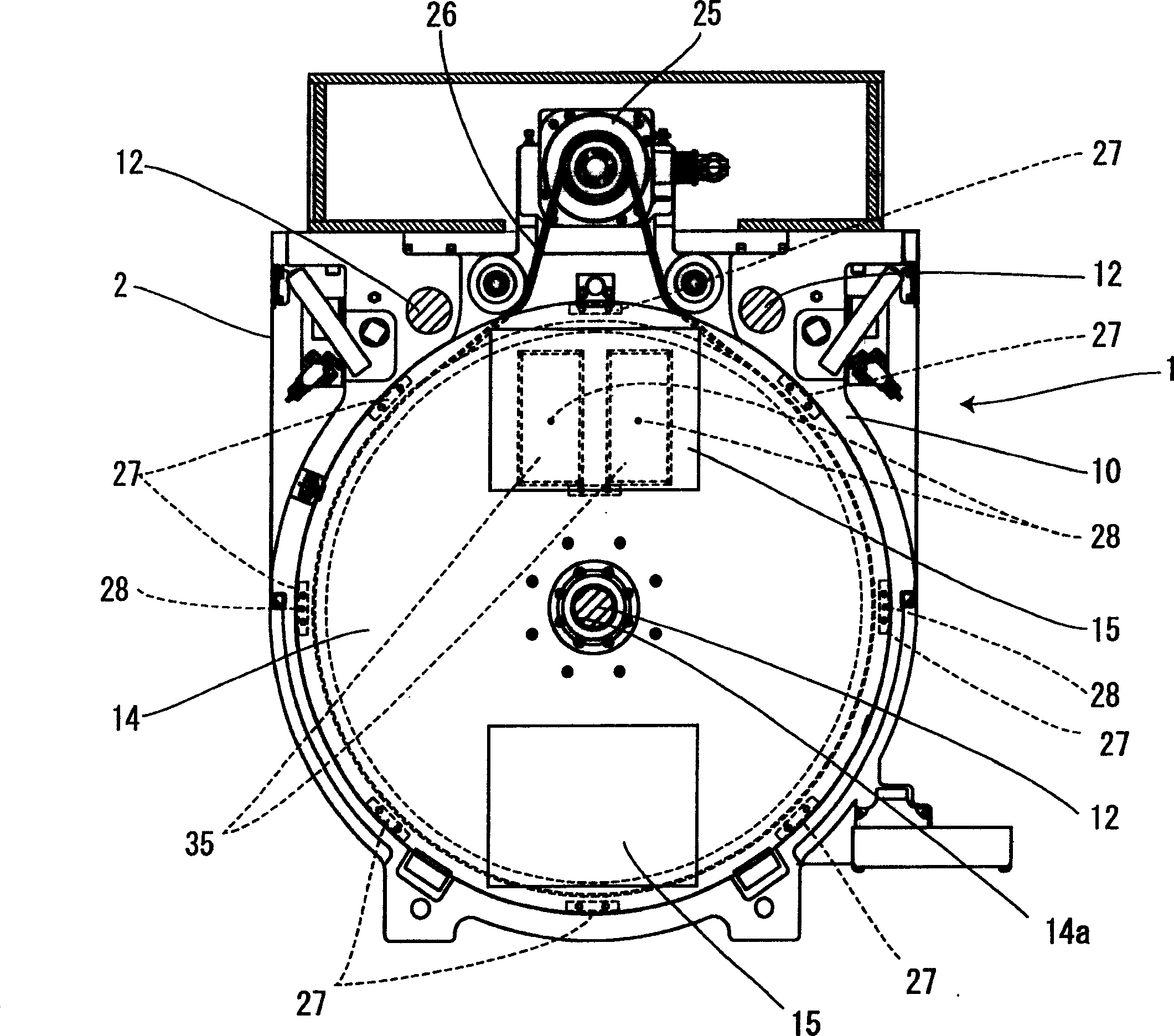
[0033] Below, through Figure 1 to Figure 5 Examples as the best mode for carrying out the present invention will be described below. Needless to say, the present invention can be easily applied to structures other than those described in the examples within a range not inconsistent with the gist of the present invention.

[0034] figure 1 It is a front view showing an example of the vertical injection molding machine of the present invention. figure 2 It is a top view of the vertical injection molding machine. image 3 It is a sectional view showing the main part of the vertical injection molding machine viewed from above. Figure 4 It is a sectional view showing the main parts of the vertical injection molding machine. Figure 5 It is a graph showing the stopping accuracy of the turntable.

[0035] figure 1 The shown vertical injection molding machine 1 opens and closes a mold in the vertical direction, and molds a molded body in which an insert member such as a met...


PUM


Abstract

The invention provides a vertical injection molding machine capable of stopping the repeatedly revolved turntable at predetermined positions. During operation of a vertical injection molding machine (1) having one or more lower molds (15) mounted on a turntable (14) and an upper mold (16) mounted on an upper retention plate (13), lubricant is periodically fed from a pump (30) to a slide portion (S) of the revolving turntable (14). Thereby, the slide resistance of the sliding portions (S) of the turntable (14) is maintained constant, by which the repeatedly revolved turntable (14) is enabled to stop accurately at predetermined positions. Thus, the present machine enables the lower molds (15) which are repeatedly clamped with the upper mold (16) to stopped at the predetermined position.

Description

technical field [0001] The present invention relates to a vertical injection molding machine that opens and closes the mold in the longitudinal direction to form a molded body, and particularly relates to a regulation that can be performed while closing the mold when the lower mold that rotates with the turntable is stopped. Vertical injection molding machine with position stop turntable. Background technique [0002] Conventionally, a so-called two-station type vertical injection molding machine has been used. By rotating the turntable, each of the two lower molds mounted on the turntable can be moved to a position where the mold can be opened and closed relative to one upper mold. The opposite position, and carry out the mold clamping in the longitudinal direction. In vertical injection molding machines such as the so-called two-station system in which such an upper mold and a plurality of lower molds are clamped, a manufacturing method has been adopted in which the Meta...

Claims


Application Information

Patent Timeline
IPC IPC(8): B29C45/83B29C45/76B29C45/06B29C45/64
Inventor 国松清
Owner TOYO MACH & METAL CO LTD
Learn More