
Bi-directional movement rotatable stamping die

A stamping die, two-way moving technology, applied in non-rotational vibration suppression, forming tools, manufacturing tools, etc., can solve problems such as reducing equipment work efficiency and inconvenient stamping methods, reducing noise pollution, halving moving distance, and increasing usage. effect of life

Active Publication Date: 2018-09-28
淮安剀立模具制造有限公司
View PDF5 Cites 6 Cited by
  • Summary
  • Abstract
  • Description
  • Claims
  • Application Information

AI Technical Summary

Problems solved by technology

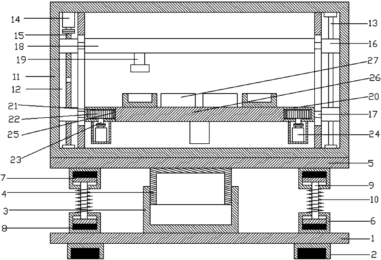
[0004] The structure of the current stamping die is that the bottom mold base is fixed, so that the stamping head is driven by the lifting equipment for stamping. This stamping method is very inconvenient, and during stamping, it is necessary to take out the stamping parts inside the lower mold base, which is also Will reduce the working efficiency of the equipment

Method used


Image

  • Bi-directional movement rotatable stamping die
  • Bi-directional movement rotatable stamping die
  • Bi-directional movement rotatable stamping die

Examples


Embodiment Construction

[0018] It should be noted that, in the case of no conflict, the embodiments of the present invention and the features in the embodiments can be combined with each other.

[0019] In describing the present invention, it should be understood that the terms "center", "longitudinal", "transverse", "upper", "lower", "front", "rear", "left", "right", " The orientations or positional relationships indicated by "vertical", "horizontal", "top", "bottom", "inner" and "outer" are based on the orientations or positional relationships shown in the drawings, and are only for the convenience of describing the present invention and Simplified descriptions, rather than indicating or implying that the device or element referred to must have a particular orientation, be constructed and operate in a particular orientation, and thus should not be construed as limiting the invention. In addition, the terms "first", "second", etc. are used for descriptive purposes only, and should not be understood ...


PUM


Abstract

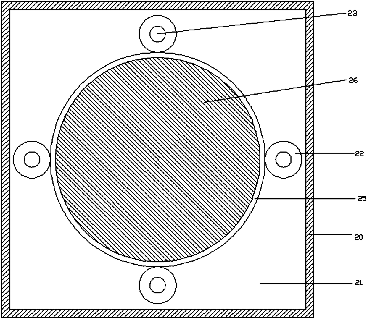
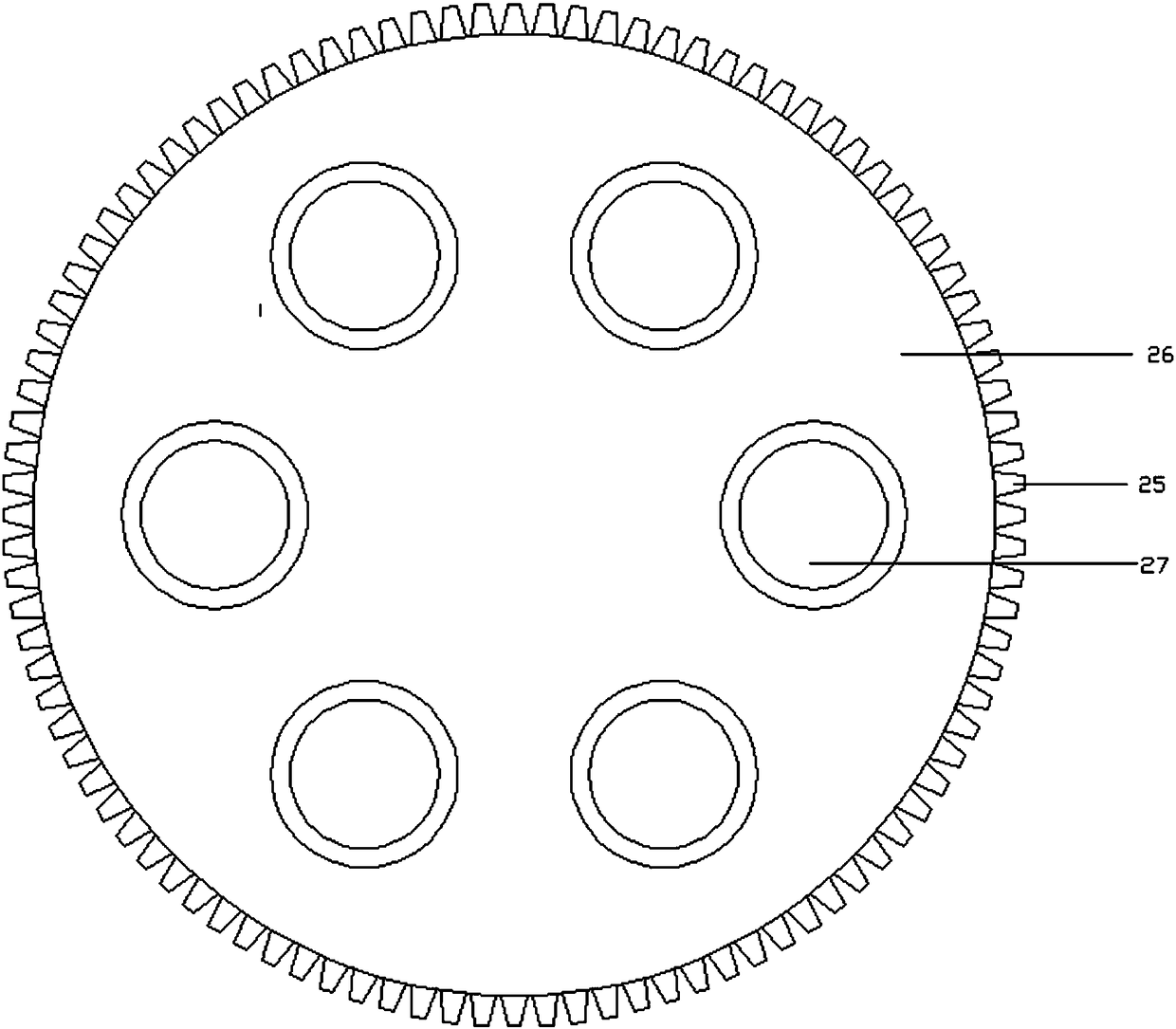
The invention discloses a bi-directional movement rotatable stamping die which comprises a bottom plate. A first connecting cover is arranged in the middle of the upper side of the bottom plate; a second connecting cover is arranged on the upper side of the first connecting cover; a support plate is arranged on the upper side of the second connecting cover; an installation frame is arranged on theupper side of the support plate; sliding chutes are formed in the left end and the right end of the inner part of the installation frame; a polish rod is arranged in the sliding chute at the right end; a screw rod is arranged in the sliding chute at the left end; the upper ends and the lower ends of the screw rod and the polish rod are arranged on slide blocks; support rods are arranged on the inner sides of the slide blocks; a connecting plate is arranged between the support rods at the upper ends; a stamping head is arranged at the left end of the lower side of the connecting plate; a fixing plate is arranged between the support rods at the lower ends; a groove is formed in the periphery of the inner part of the fixing plate; gears are arranged in the groove; connecting shafts are arranged in the gears; second motors are arranged on the lower sides of the connecting shafts; outer teeth are arranged among the gears; a rotating plate is arranged on the inner sides of the outer teeth;and a stamping die base is arranged on the upper side of the rotating plate. According to the bi-directional movement rotatable stamping die provided by the invention, the equipment can be used for stamping effectively and conveniently, so that the working efficiency of the equipment is improved, and the convenience in use by people is realized.

Description

technical field [0001] The invention relates to the field of molds, in particular to a two-way movable and rotatable stamping mold. Background technique [0002] Mold, various molds and tools used in industrial production for injection molding, blow molding, extrusion, die-casting or forging forming, smelting, stamping and other methods to obtain the required products. In short, a mold is a tool used to make shaped objects. This tool is composed of various parts, and different molds are composed of different parts. It mainly realizes the processing of the shape of the article through the change of the physical state of the formed material. Known as the "Mother of Industry". [0003] Stamping die is a special process equipment for processing materials (metal or non-metal) into parts (or semi-finished products) in cold stamping processing, called cold stamping die (commonly known as cold stamping die). Stamping is a pressure processing method that uses a mold installed on a...

Claims


Application Information

Patent Timeline
Patent Type & Authority Applications(China)
IPC IPC(8): B21D37/10B21D45/04F16F15/06
CPCB21D37/10B21D45/04F16F15/06
Inventor 黄远明
Owner 淮安剀立模具制造有限公司
Learn More