Rotor for laboratory centrifuges

A laboratory centrifuge and rotor technology, applied in the direction of centrifuges, etc., can solve the problems of moving the centrifuge container from the working position and the unbalanced operation of the centrifuge, and achieve the effect of reducing attention requirements, simplifying manufacturing, and improving operations.

Active Publication Date: 2006-08-23
QIAGEN GMBH
View PDF0 Cites 16 Cited by
  • Summary
  • Abstract
  • Description
  • Claims
  • Application Information

AI Technical Summary

Problems solved by technology

During loading or unloading, or during operation, the centrifuge container may be accidentally moved out of the working position
Especially when the sample container is removed, the adapter with the sample container in it can be inadvertently removed from the rotor together with the sample container
Also, inadvertently removing the centrifuge container from the annular groove, or touching and manipulating the centrifuge container in the annular groove may cause the centrifuge to run unevenly

Method used


Image

  • Rotor for laboratory centrifuges
  • Rotor for laboratory centrifuges
  • Rotor for laboratory centrifuges

Examples


Embodiment Construction

[0046] In the various embodiments of the present invention shown in the figures, the same components are marked with the same reference numerals.

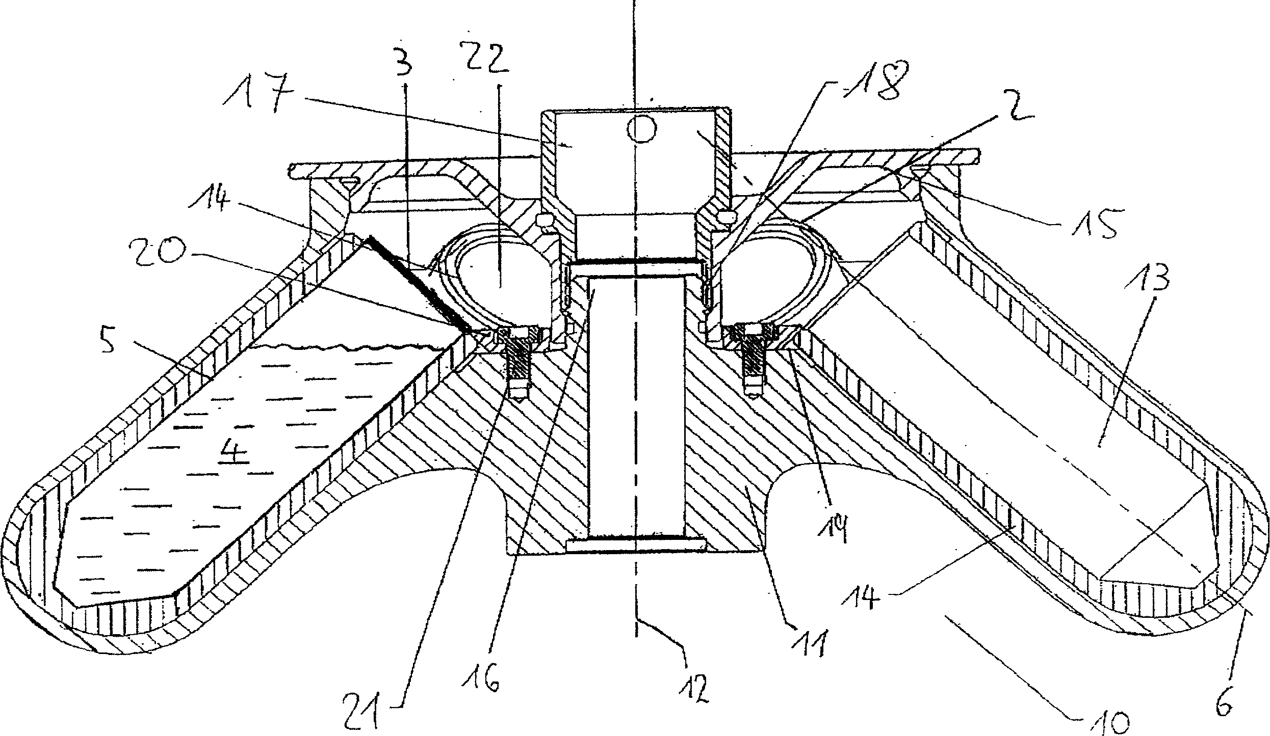
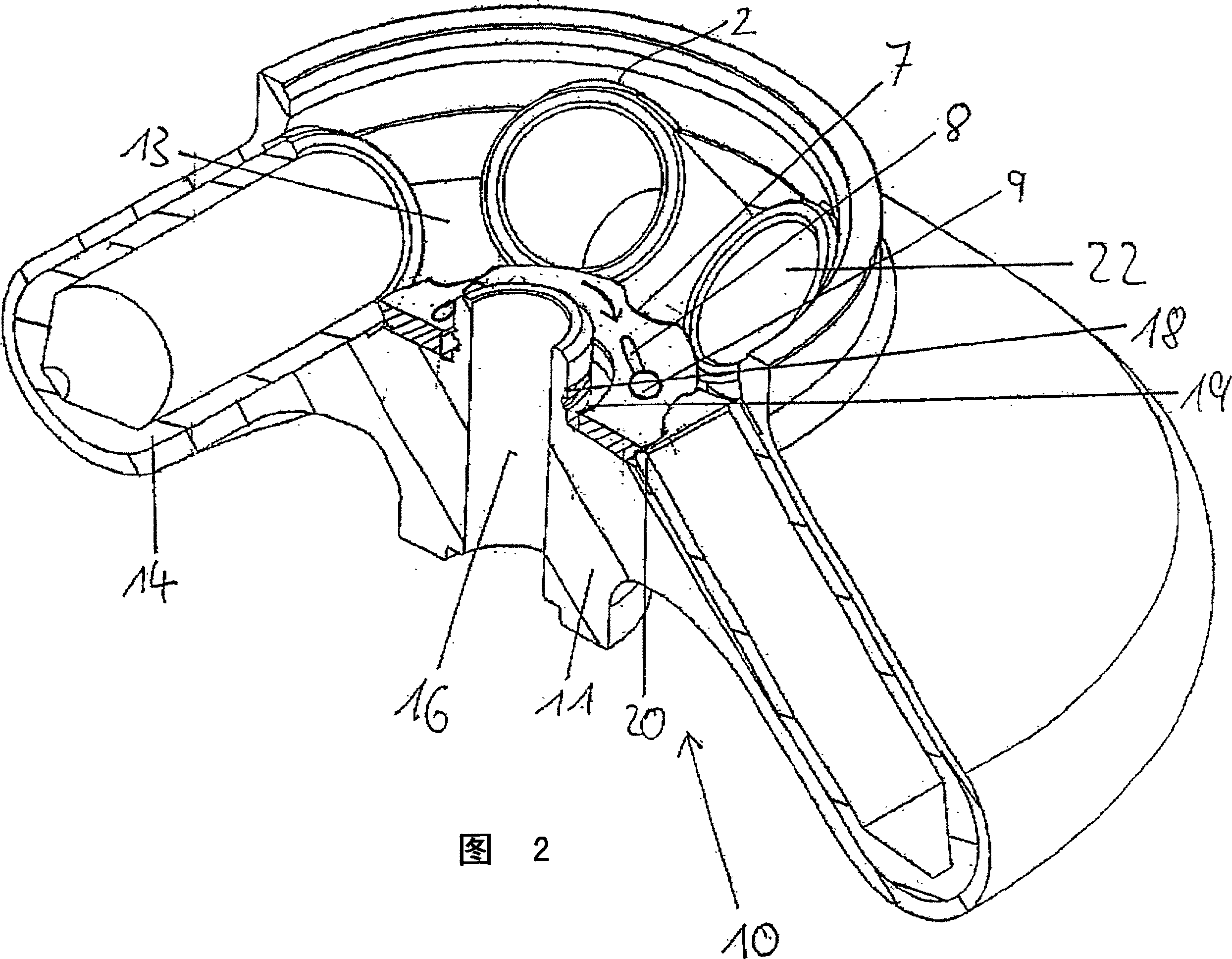
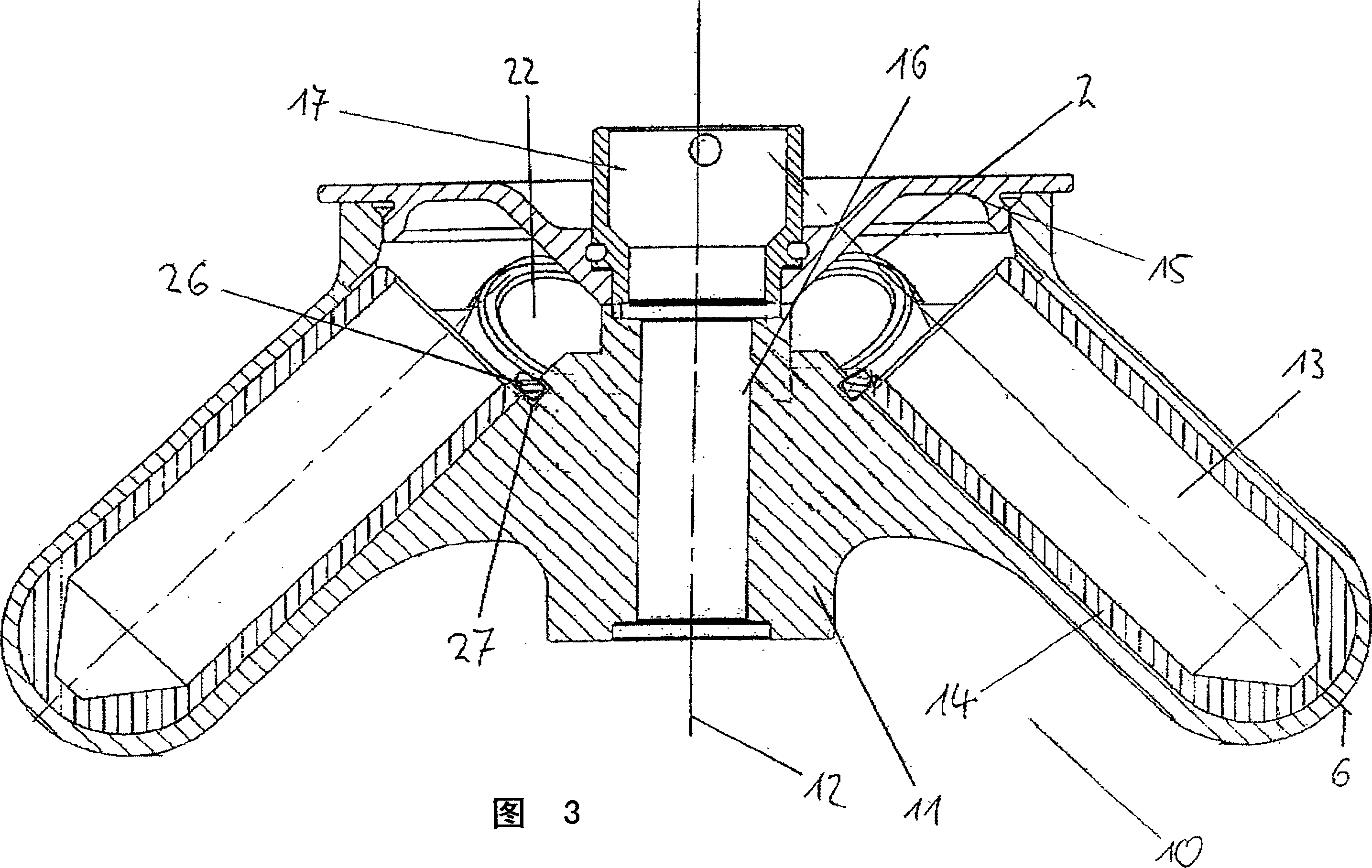
[0047] figure 1 is the cross-section of the rotor 10 of the laboratory centrifuge. The rotor 10 has a frusto-conical shape with a rotor body 11 which is frusto-conical upwards. Annular grooves 13 , surrounding the rotor shaft 12 , are arranged in the outer area of ​​the rotor 10 . In the annular groove 13 , adapters are arranged at regular intervals in the circumferential direction, designed to accommodate the sample containers 5 . The sample container 5 has a cover 3 at its upper end and contains a sample solution 4 .

[0048] The adapter 14 is generally designed as a hollow cylinder with a closed bottom and an opening on the upper end. The outer wall of the annular groove has arcuate recesses 2 designed to receive one adapter 14 each in a positive fit and to fix the adapters 14 in the circumferential direction. The adapter 1...


PUM


Abstract

The invention relates to a rotor for laboratory centrifuges which is designed for accommodating at least one centrifugation container, and an adapter for accommodating a sample vessel and for use in a laboratory centrifuge rotor. The rotor has at least one hold-down element by which the at least one centrifugation container is held in the rotor and protected from axial displacement. In addition, a contact pressure may be produced on the at least one centrifugation container on the rotor.

Description

technical field [0001] The invention relates to a rotor for a laboratory centrifuge designed to accommodate at least one centrifuge container and an adapter for accommodating a sample container and for a laboratory centrifuge rotor. Background technique [0002] In this context, the centrifuge container can firstly be a sample container in which the sample to be centrifuged is placed. On the other hand, the centrifuge container can also be inserted into the rotor by the adapter and the sample container can be placed therein. [0003] The invention preferably relates to a fixed-angle rotor with a circumferential annular groove located annularly around the rotor shaft, which is designed as an annular groove. The annular groove is designed to accommodate the centrifuge container. Each centrifuge container is circumferentially located in the annular groove with a certain distance from each other, and is inclined inwardly at a predetermined angle with respect to the rotor shaft...

Claims


Application Information

Patent Timeline
Patent Type & Authority Applications(China)
IPC IPC(8): B04B5/12B04B5/04B04B15/00
CPCB04B7/08B04B2007/025B04B5/0414B04B5/0407
Inventor 弗兰克·艾格梅尔
Owner QIAGEN GMBH
Why Eureka
Try Eureka