Lock core device for anti-pry and anti-universal key

A master key and lock cylinder technology, used in locks with turning keys, construction locks, cylinder locks, etc.

Inactive Publication Date: 2006-08-23
吴建金
View PDF0 Cites 3 Cited by
  • Summary
  • Abstract
  • Description
  • Claims
  • Application Information

AI Technical Summary

Problems solved by technology

The disadvantage of the above-mentioned lock cylinder device is that the lock tongue is directly driven by the lock cylinder rotor, and the lock can be unlocked as long as the lock cylinder rotor is rotated, and the lock cylinder rotor is easy to use the master key to move the pins or blades so that all the pins or blades are pushed in an instant. Unlock from the blocking position; or use a special tool such as a screwdriver to forcibly turn the lock cylinder rotor to twist off the pins or blades to separate the lock cylinder rotor from the lock cylinder fixing seat for unlocking

Method used


Image

  • Lock core device for anti-pry and anti-universal key
  • Lock core device for anti-pry and anti-universal key
  • Lock core device for anti-pry and anti-universal key

Examples


Embodiment 1

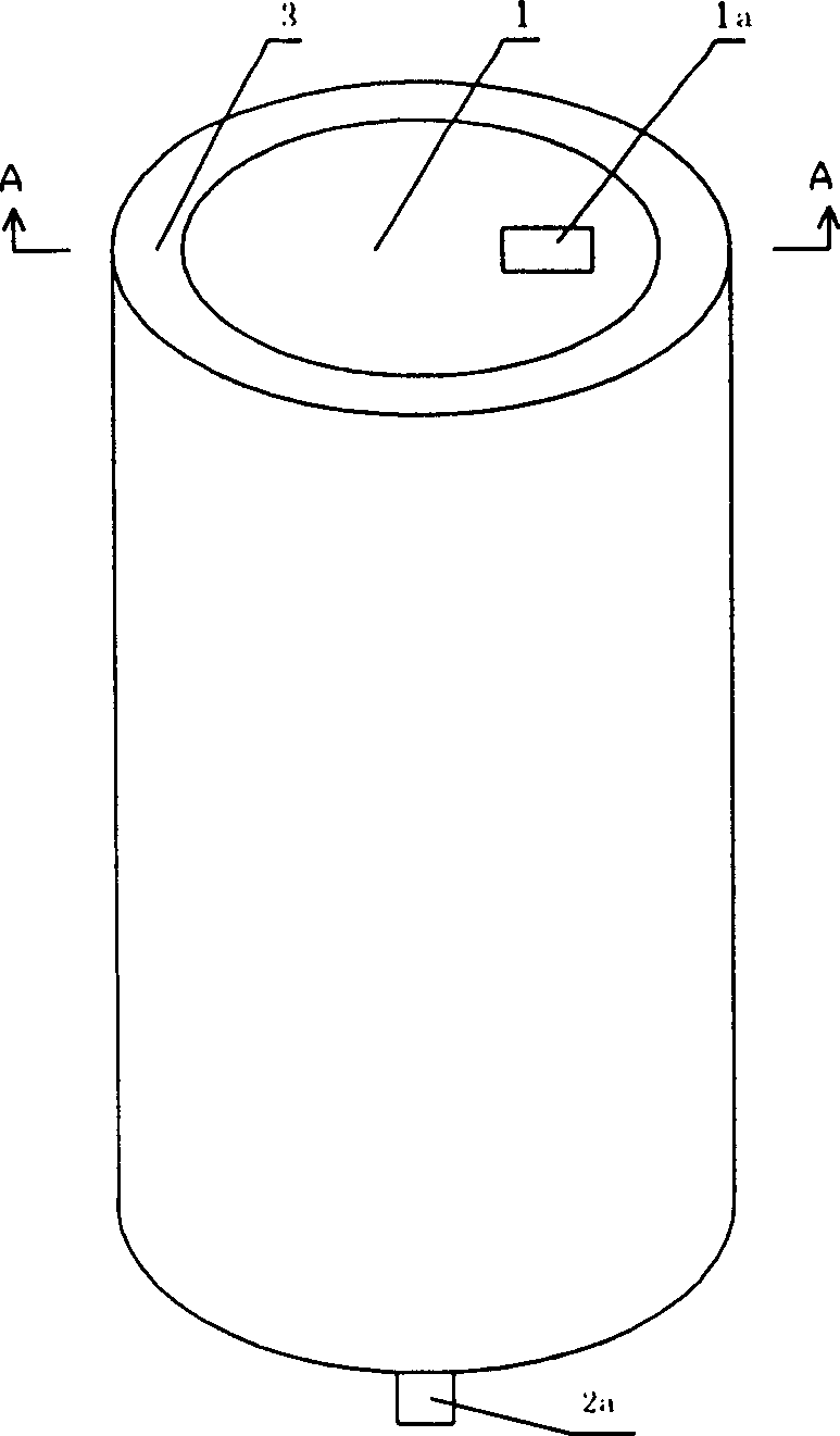
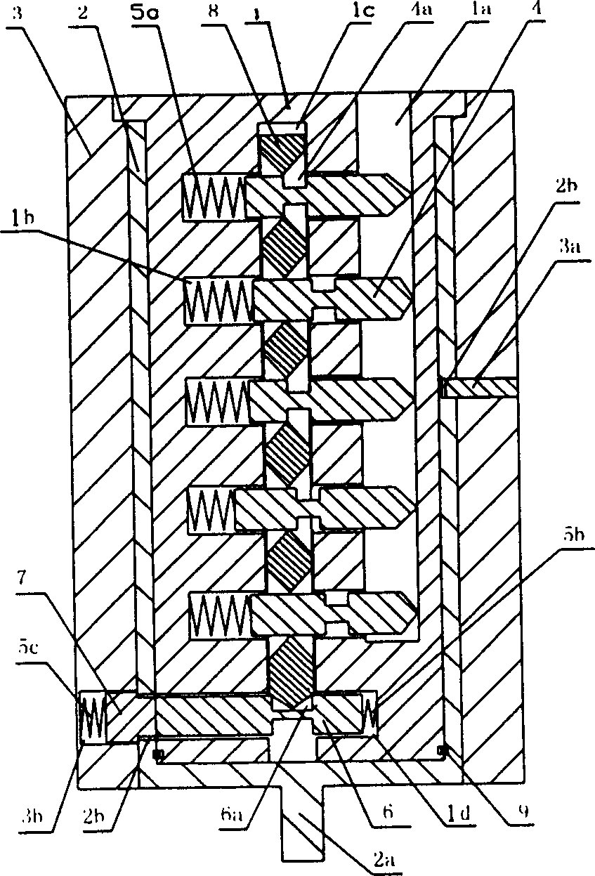
[0038] Embodiment 1: with reference to attached figure 1 , 2 , 3, 4, 5, 6, 7. It can be seen from the figure that the inner lock cylinder 1 is rotatably fitted in the outer lock cylinder 2, and the outer lock cylinder 2 is fitted in the tubular lock cylinder fixing seat 3; the upper end of the inner lock cylinder 1 is provided with an outer flange, assembled Finally, the outer flange covers the outer lock core 2; the bottom surface of the outer lock core is provided with a lock bolt 2a, and the dead bolt can be moved to unlock by turning the lock bolt 2a. The lower ends of the inner lock core 1 and the outer lock core 2 are nested together by the elastic collar 9; a section of horizontal groove 2b is provided along the outer circumferential surface of the outer lock core 2, and the side wall of the lock core fixing base 3 is correspondingly fixed. There is a limit pin 3a, and the inner end of the limit pin 3a extends into the horizontal groove 2b to limit the rotation angle ...

Embodiment 2

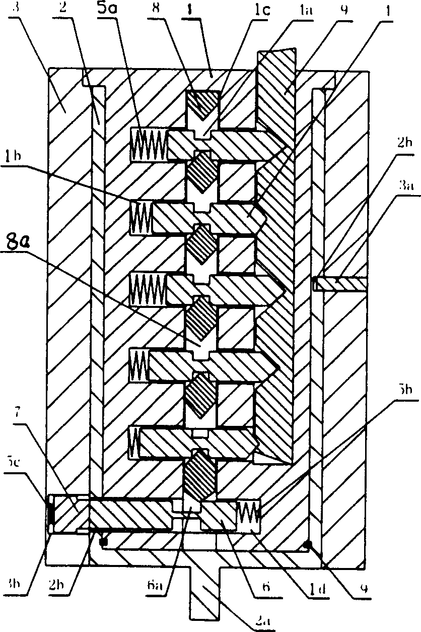
[0043] Embodiment 2: with reference to attached Figure 8 , 9 , 10, 11, 1213, 14, 15, 16. The difference between this embodiment and Embodiment 1 is that the inner lock cylinder 1 is provided with a rectangular blade groove 1e, and each blade groove 1e is respectively provided with two generally L-shaped blades 41, and the two blades 41 are placed opposite to the blade groove 1e. There is a distance 41b between the front end convex parts of the blades and the opposing surfaces of the notch parts at the rear ends. Wedge-shaped grooves 41a are respectively provided at specific positions on the lower parts of the notch parts of the two blades 41. According to the wedge-shaped concave parts of each blade, The different positions of the groove 41a form different password combinations. Return springs 5a are respectively arranged between the rear end surfaces of the two blades 41 and the bottom surface of the blade groove 1e, and each blade can move radially. The movable pin slot 1...

Embodiment 3

[0045] Embodiment 3: with reference to attached Figure 17 , 18 , 19, 20, 21, 22, 23, 24. The difference between this embodiment and Embodiment 2 is that a plurality of annular blade grooves 1f are arranged on the peripheral surface of the inner lock cylinder 1, and two arc-shaped blades 42 are respectively arranged in each blade groove 1f. The sum of the lengths of 42 is less than the perimeter of the blade groove 1f, the two blades 42 can slide towards each other along the blade groove, the two blades 42 are relatively placed on both sides of the blade groove 1f, and the specific positions of the opposite surfaces of the two blades 42 are respectively provided with The wedge-shaped groove 42a and the return spring 5a are supported between the rear end surfaces of the two blades 42 . The inner lock core 1 at the bottom of the blade groove 1f is fixed with a limiting convex portion 1g, and the inner side of the front end surface of the blade 42 is correspondingly provided wi...


PUM


Abstract

The lock core device capable of preventing pick and resisting universal key includes an inner lock core, an outer lock core and a lock core fixing seat connected successively. The outer lock core is provided with lock bolt to shift the lock tongue in the bottom. The inner lock core is provided with balls or blades and movable pins, the balls or blades are provided with code aligning part in the specific position, the movable pins are provided with corresponding joint part, and the code aligning part and the joint part are cooperated to locate the movable pins axially and locate the normal contact surface between the driving pins and the locking pins radially. Before the correct key is inserted, the inner lock core may be rotated freely, and this can avoid the test with universal key and the pick with some tool, such as a screw driver.

Description

technical field [0001] The invention relates to the technical field of lock cylinders, in particular to an anti-prying and anti-master lock cylinder device. Background technique [0002] The existing lock cylinder device mainly includes a hollow lock cylinder sleeve, a lock cylinder rotor installed in the lock cylinder sleeve, and lock cylinder pins or blades respectively installed in the storage grooves of the lock cylinder sleeve and the lock cylinder rotor. Push the core or blade of the lock cylinder away from the blocking position through the matching key, and turn the key to drive the rotor of the lock cylinder to move the lock tongue to unlock. The disadvantage of the above-mentioned lock cylinder device is that the lock tongue is directly driven by the lock cylinder rotor, and the lock can be unlocked as long as the lock cylinder rotor is rotated, and the lock cylinder rotor is easy to use the master key to move the pins or blades so that all the pins or blades are pu...

Claims


Application Information

Patent Timeline
Patent Type & Authority Applications(China)
IPC IPC(8): E05B27/02E05B29/06
Inventor 吴建金
Owner 吴建金
Why Eureka
Try Eureka