
Hand-held image acquisition system and its controlling method

An image capture, hand-held technology, applied in the computer field, can solve the problems of occupying display space, difficult to operate, and increase the production cost of the camera, and achieve the effect of reducing the number of keys, reducing the complexity, and reducing the production cost.

Inactive Publication Date: 2006-09-06
ASIA OPTICAL CO INC
View PDF0 Cites 7 Cited by
  • Summary
  • Abstract
  • Description
  • Claims
  • Application Information

AI Technical Summary

Problems solved by technology

[0003] These operation buttons are distributed on the surface of the digital camera, which will not only occupy the space of the display and limit the size of the display, but also increase the production cost of the camera
[0004] In addition, since many advanced functions of the digital camera need to be realized by operating multiple menus on the display, this will increase the complexity of using the function program, especially for some users (such as the elderly). operate

Method used

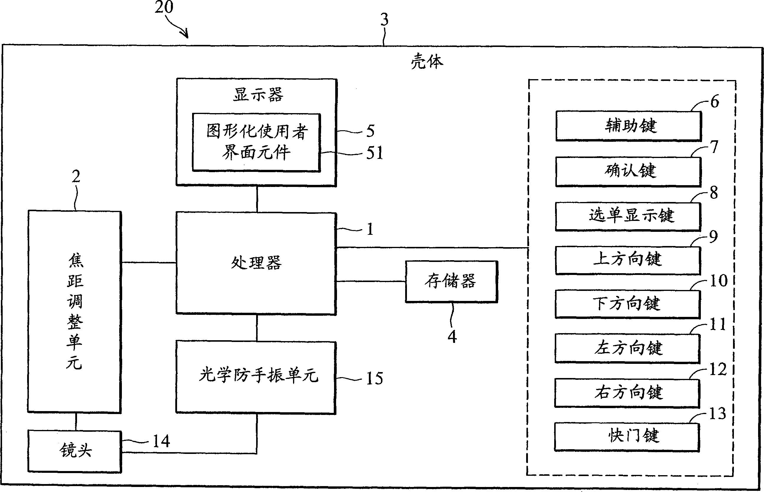
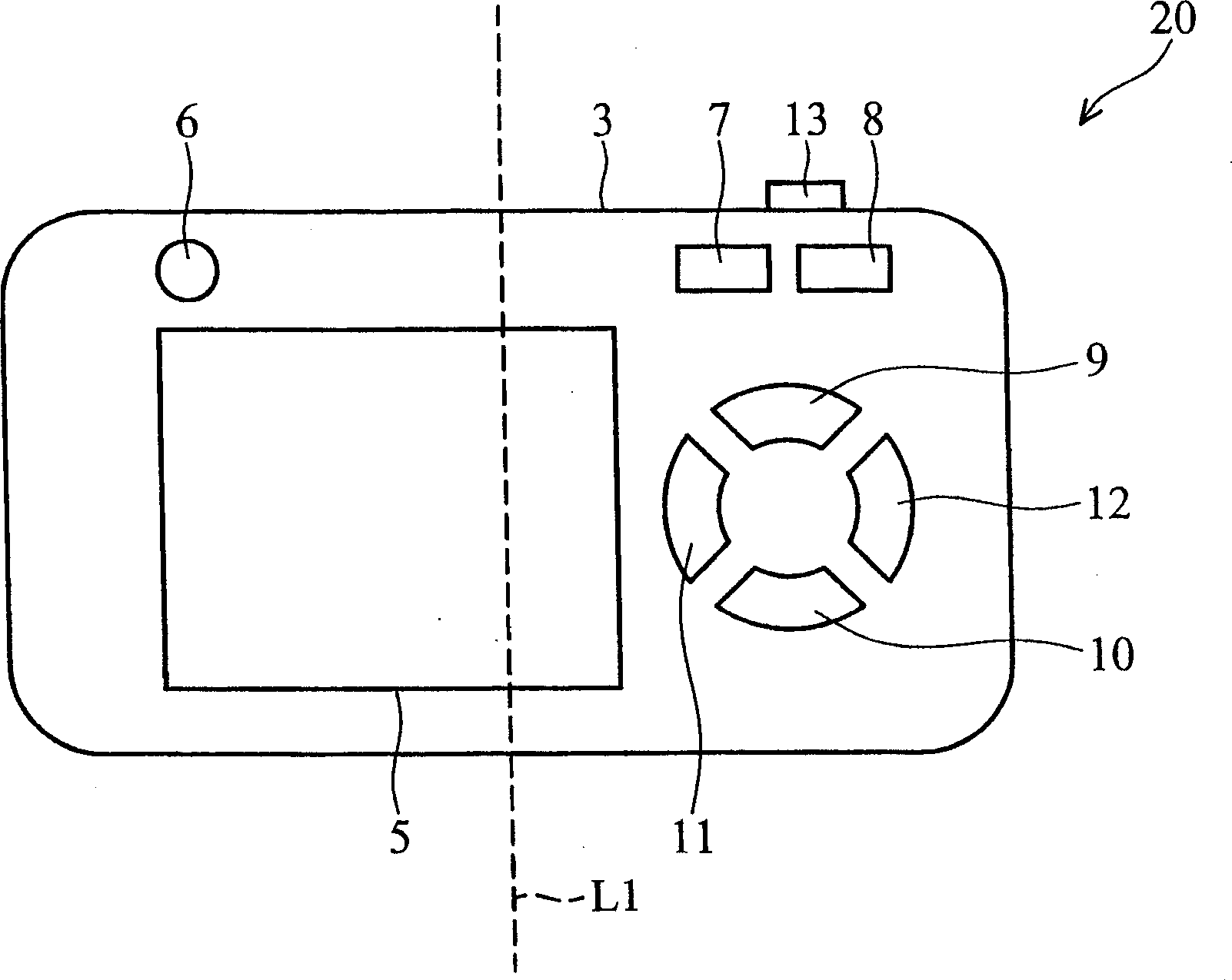
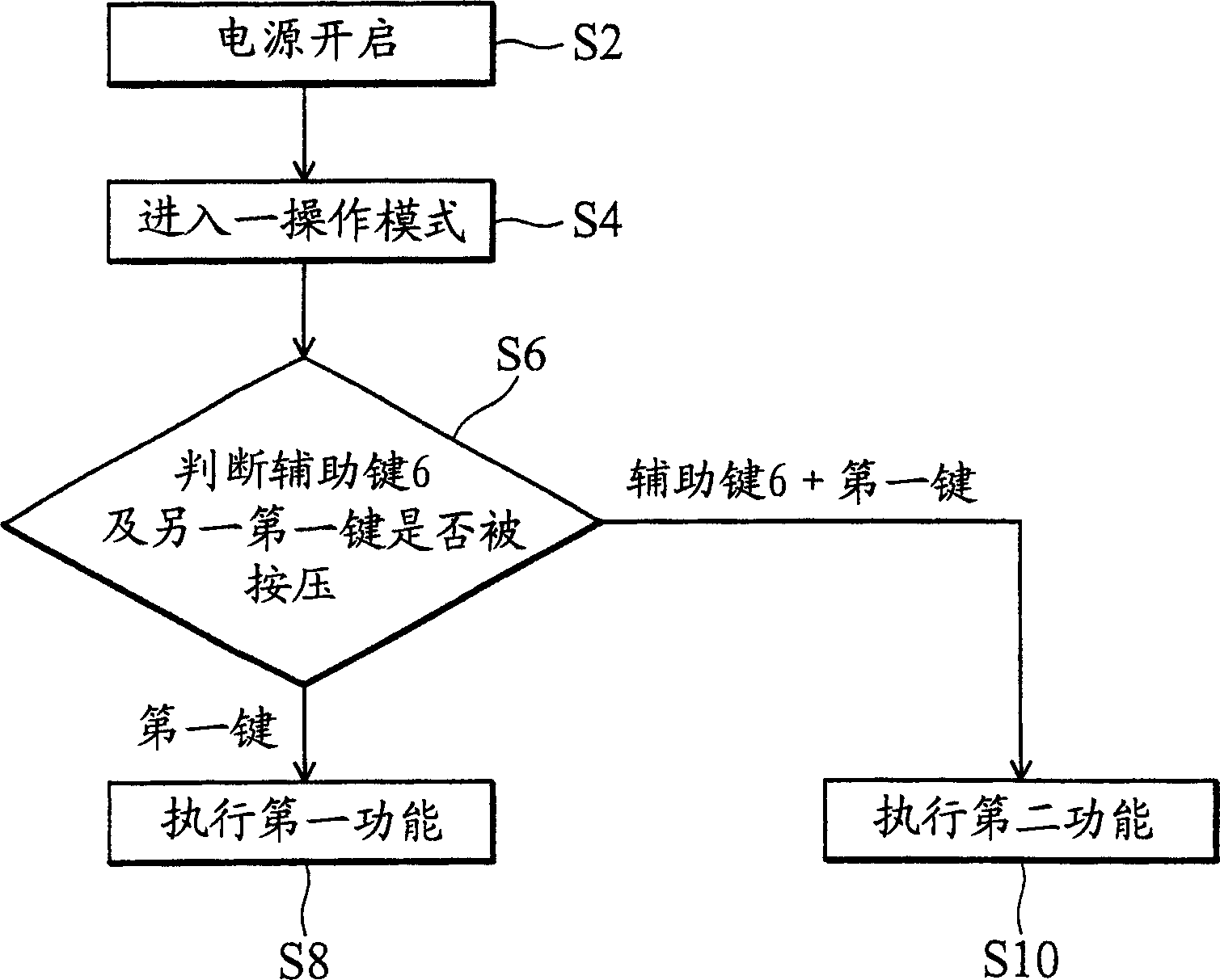

Image

  • Hand-held image acquisition system and its controlling method
  • Hand-held image acquisition system and its controlling method
  • Hand-held image acquisition system and its controlling method

Examples


example 1

[0042] The above-mentioned first operation mode is a photography mode, and the above-mentioned first key is a direction key (such as up, down, left and right keys 9-12). When the auxiliary key 6 is not pressed and the above-mentioned direction key is pressed, the processor 1 moves the display A graphical user interface element on the display. When the auxiliary key 6 and the direction key are pressed simultaneously, the processor 1 adjusts the focal length of the lens.

[0043] For example, the above-mentioned first key is an up arrow key 9 , and in step S8 , the processor 1 moves the above-mentioned GUI element 51 to the top of the display 5 . In step S10 , the processor 1 uses the focus adjustment unit 2 and the lens 14 to perform zoom-in.

[0044] If the above-mentioned first key is the down arrow key 10, in step S8, the processor 1 moves the above-mentioned GUI element 51 to the bottom of the display 5. In step S10 , the processor 1 uses the focus adjustment unit 2 and t...

example 2

[0046] The above-mentioned first key is a direction key. When the auxiliary key 6 is not pressed and the above-mentioned direction keys (such as up, down, left and right keys 9-12) are pressed, the processor 1 is used to move a GUI element displayed on the display 5 51. When the auxiliary key 6 and the above-mentioned direction key are pressed at the same time, the processor 1 switches the operation mode of the handheld image capture system 20 , such as photography mode, dynamic image capture mode and playback mode.

example 3

[0048] The above-mentioned first operation mode is a photography mode, and the above-mentioned first key is a direction key (for example, up, down, left, and right keys 9-12). When the auxiliary key 6 is not pressed and the direction key is pressed, the processor 1 is used to move a GUI element 51 displayed on the display 5 . When the auxiliary key 6 and the above-mentioned direction key are pressed at the same time, the processor 1 switches the shooting scene mode (Scene mode) of the above-mentioned handheld image capture system 20, such as portrait (Portrait), landscape (Landscape), dynamic photography (Sports) , Night Photography (NightPortrait) and automatic adjustment (Auto).


PUM


Abstract

The present invention refers to hand held image taking system and control method. Said hand held image taking system is in first operator schema in power supply turn-on state, and containing first key, auxiliary key and processor. Said processor is coupled with above-mentioned auxiliary key and first key for judging whether said auxiliary key and first key are pressed. When above-mentioned auxiliary key is not pressed but first key is pressed, above-mentioned processor drives above-mentioned first function of first operation mode. When above-mentioned auxiliary key and first key simultaneously pressed, above-mentioned processor drives second function different with above-mentioned first function in first operation mode. The present invention provided system and control method can reduce press key number, thereby reducing manufacture cost and reducing complexity of using function program.

Description

technical field [0001] The present invention relates to computer technology, and in particular to a hand-held image capture system and its control method. Background technique [0002] The size of digital cameras currently on the market tends to be smaller and smaller, however, they still maintain a consistent number of basic key switches (about 9 to 11 keys), that is, including up, down, left, and right Arrow keys, confirmation key, power switch, shutter key, half-shutter key, menu display key, zoom in focus, and zoom out focus keys. [0003] These operation buttons are distributed on the surface of the digital camera, which will not only occupy the space of the display and limit the size of the display, but also increase the production cost of the camera. [0004] In addition, since many advanced functions of the digital camera need to be realized by operating multiple menus on the display, this will increase the complexity of using the function program, especially for so...

Claims


Application Information

Patent Timeline
IPC IPC(8): H04N5/225H04N5/232
Inventor 詹胜吉翁于昌
Owner ASIA OPTICAL CO INC
Learn More