Back flow preventer

A technology of backflow prevention and check valve, which is applied in the direction of valve operation/release device, function valve type, transportation and packaging, etc. It can solve the problem of backflow preventer cleaning machine damage and achieve the effect of small structure volume

Inactive Publication Date: 2006-09-06
ALFRED KARCHER GMBH & CO KG
View PDF1 Cites 10 Cited by
  • Summary
  • Abstract
  • Description
  • Claims
  • Application Information

AI Technical Summary

Problems solved by technology

In this position, however, a rise in pressure in the outlet area of ​​the backflow preventer may cause damage to the backflow preventer or a cleaning machine connected to it.
This increase in pressure can occur, for example, briefly as a pressure spike in a high-pressure cleaner if the high-pressure cleaner is switched off

Method used


Image

  • Back flow preventer
  • Back flow preventer

Examples


Embodiment Construction

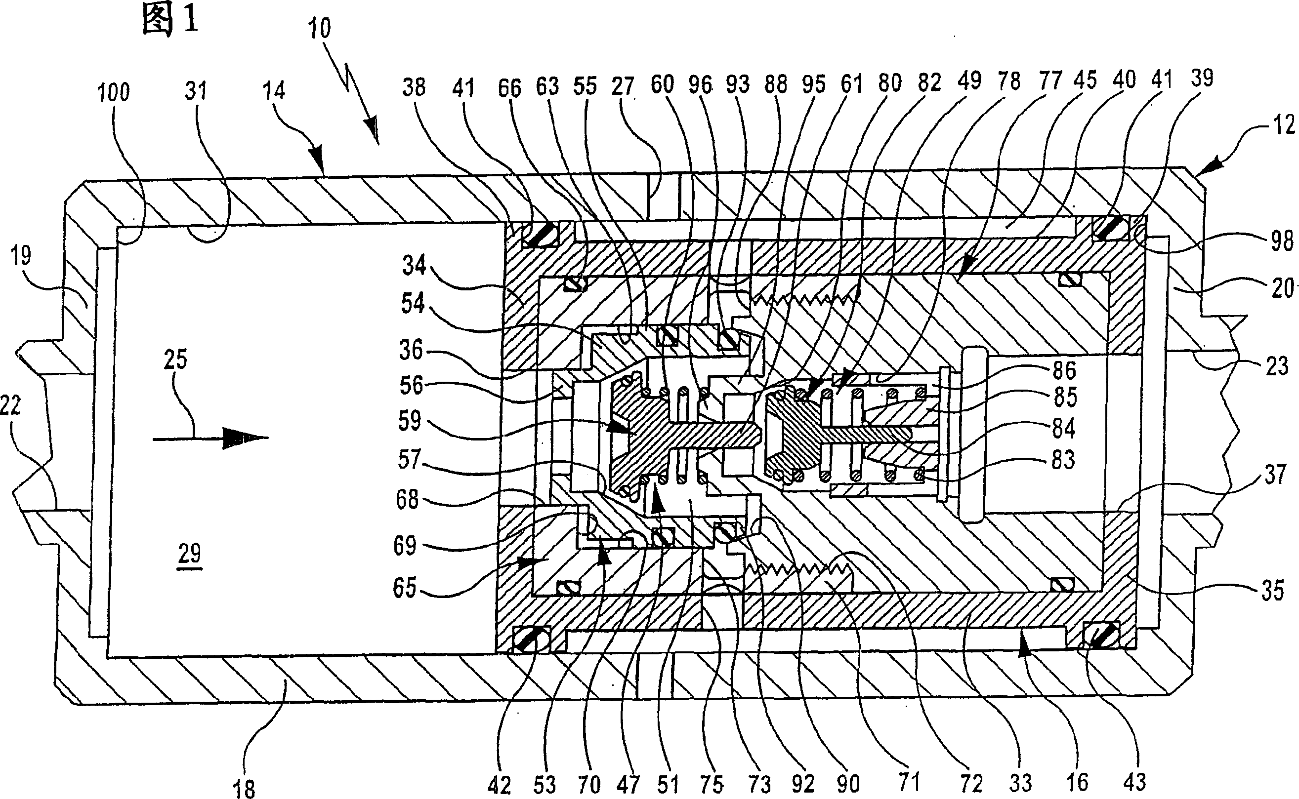
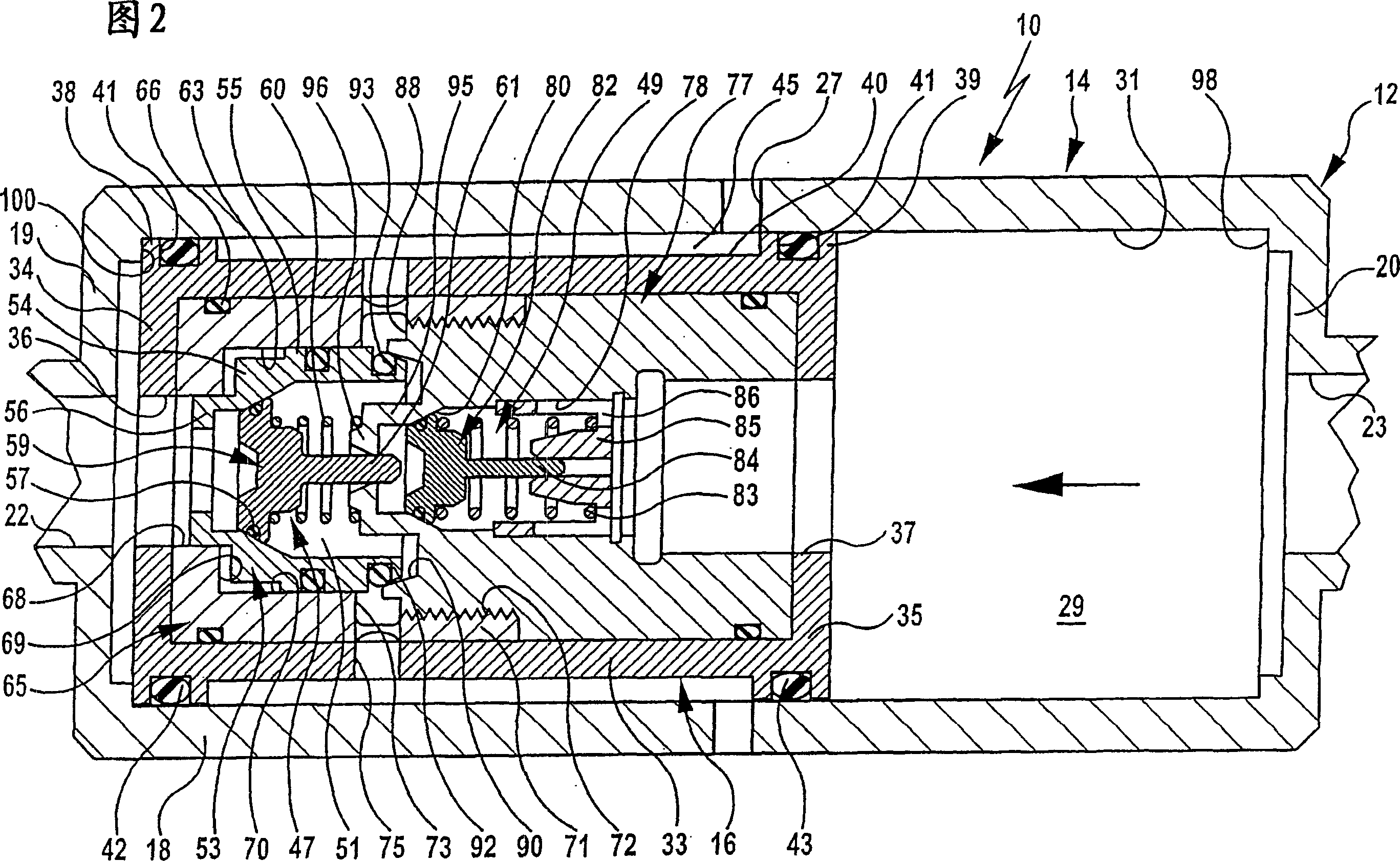
[0026] There is shown a backflow preventer, generally designated by the reference numeral 10 , having a two-piece housing 12 with a hollow cylindrical outer shell 14 and an inner shell 16 movably retained within the outer shell 14 .

[0027] The housing 14 has a housing cylinder 18 which is connected to a housing top 19 and a housing bottom 20 . An inlet 22 is formed on the housing top 19 and an outlet 23 is formed on the housing bottom 20 . At least one, in particular a plurality of leakage openings 27 distributed over its circumference are formed on the housing cylinder 18 approximately centrally between the inlet 22 and the outlet 23 in the flow direction 25 .

[0028] The outer shell 14 encloses a receiving area 29 in which the inner shell 16 is held reciprocally movable in the flow direction 25 .

[0029]The inner casing 16 is also designed as a hollow cylinder and includes a sleeve 33 arranged at a certain distance from the inner wall 31 of the casing tube 18, which is ...


PUM


Abstract

Disclosed is a backflow preventer comprising a housing which is provided with an inlet port, an outlet port, and at least one leakage opening that is located between said ports. The housing accommodates two first check valves which are arranged one behind the other. The first check valve is movably retained for opening or blocking a flow connection between an intermediate space of the housing and the leakage opening. In order to prevent, in a simple structural manner, the pressure from unduly increasing in the area of the outlet port, the housing encompasses an inner housing and an outer housing. The outer housing is provided with the at least one leakage opening while the inner housing accommodates the two check valves and is retained within the outer housing so as to be movable in the direction of flow. Furthermore, the inner housing comprises an outlet port via which the flow connection between the intermediate space and the leakage opening can be established regardless of the position of the inner housing by displacing the first check valve.

Description

technical field [0001] The invention relates to a backflow preventer, in particular for connecting a high-pressure cleaner to a drinking water supply line, comprising a housing with an inlet, an outlet and at least one device arranged in the direction of flow between the inlet and the outlet. The leak hole, and accommodate a first and a second non-return element, they are arranged in sequence along the flow direction, wherein the first non-return valve is movably fixed to open or close a set of two non-return valves of the housing The flow connection between the intermediate cavity and the leak hole. Background technique [0002] Such a backflow preventer is also known as a "line interrupter" and is known from laid-open document DE 2424978 A1. They are used in washing machines, especially high pressure washers or washing machines. If such a washing machine is connected to a drinking water supply line, it must be ensured that contaminated washing liquid cannot flow back fro...

Claims


Application Information

Patent Timeline
Patent Type & Authority Applications(China)
IPC IPC(8): E03C1/10F16K15/06F16K31/122
CPCE03C1/106E03C1/10F16K31/1226F16K15/066E03C1/108Y10T137/3331
Inventor W·米勒
Owner ALFRED KARCHER GMBH & CO KG
Why Eureka
Try Eureka