
Image forming method and image forming apparatus

An image and recording device technology, applied in the direction of printing device, printing, etc., can solve the problem that the surface of the sheet cannot be used, and achieve the effect of effective utilization

Inactive Publication Date: 2006-09-27
CANON KK
View PDF1 Cites 5 Cited by
  • Summary
  • Abstract
  • Description
  • Claims
  • Application Information

AI Technical Summary

Problems solved by technology

Since these areas are non-printing areas, the entire surface of the sheet cannot be utilized

Method used


Image

  • Image forming method and image forming apparatus
  • Image forming method and image forming apparatus
  • Image forming method and image forming apparatus

Examples


Embodiment Construction

[0025] Now, an image forming method and an image forming apparatus according to an embodiment of the present invention will be described in detail herein with reference to the accompanying drawings.

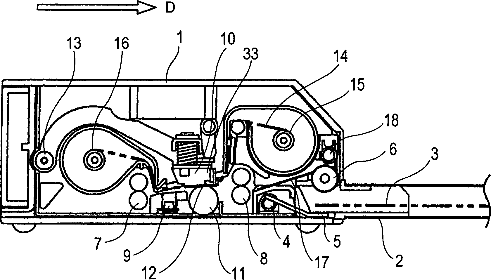
[0026] figure 1 The main parts of a thermal printer 1 as an example of an image forming apparatus are illustrated. Image information is transmitted from an upper system including a digital device such as a personal computer or a digital camera or a host computer to a control section (not shown) of the thermal printer 1 through, for example, a connecting cable. Upon receiving the image information, the control section starts a recording operation to form an image on the sheet 3 as recording paper.

[0027] Sheets 3 accommodated in paper feed tray (feeding section) 2 are pressed against feed rollers 6 by upper / lower plates 5 that swing up and down about upper / lower plate shafts 4 . The rotation of the feed roller 6 picks up the sheet 3 . The sheet 3 is then fed into the device b...


PUM


Abstract

An image forming apparatus includes upstream and downstream transport rollers for transporting a recording paper sheet. The upstream transport roller is disposed on the upstream side of a recording head while the downstream transport roller is disposed on the downstream side of the recording head. When forming an image on the first half area of the recording sheet, the upstream transport roller rotates and is responsible for transporting the recording sheet. When forming an image on the second half area of the recording sheet, the downstream transport roller rotates and is responsible for transporting the sheet. This structure provides printing without margins at the leading and trailing edges of the sheet. By adjusting the gap sizes between rollers in each of the upstream and the downstream rollers, the transport speed of the sheet is maintained constant so that high-quality print image can be obtained without uneven density in an image.

Description

technical field [0001] The present invention relates to an image forming method and an image forming apparatus for a printer apparatus and a facsimile apparatus including a recording head as a recording member. Background technique [0002] In general, an ink sublimation type printer that prints image information on a sheet of chemically-treated recording paper using a thermal transfer belt has a recording head and a platen roller. The platen roller presses the sheet against the recording head when an image is formed. Inside the recording head, a plurality of heating elements are arranged in rows, and rows are arranged in parallel. The heating element is selectively heated according to the image information, so that the ink on the ink ribbon is sublimated and the image information is transferred to the recording surface of the sheet. Thus, a printing operation is performed. [0003] In this configuration, the sheet conveyance mechanism includes a power feed roller and a c...

Claims


Application Information

Patent Timeline
IPC IPC(8): B41J29/38B41J2/32B41J13/00B41J11/00
Inventor 新井纪行
Owner CANON KK
Learn More