Automatic labeling system and method for hard disk

A label and hard disk technology, applied in the system field of labeling on the hard disk, can solve the problems of increasing the labor intensity of employees, increasing the number of operators, reducing production efficiency, etc., and achieving the effect of reducing manpower, reducing labor intensity and improving production efficiency.

Inactive Publication Date: 2006-09-27
YITUO SCI & TECH CO LTD SHENZHEN
0 Cites 11 Cited by

AI-Extracted Technical Summary

Problems solved by technology

This method has the following disadvantages: 1) because all are manual operations, it not only reduces the production efficiency, but a...

Abstract

This invention relates to an automatic labeling system and method for hard disk, which comprises: a convey mechanism to convey the tray carried HD, a scanner to the HD identification bar code, a printer for label, a label operating mechanism to receive the output label and stick on HD, and a host connected all former mechanisms to control the printer to print HD information on label for output. This invention reduces labor and cost to improve efficiency.

Application Domain

Technology Topic

Image

  • Automatic labeling system and method for hard disk
  • Automatic labeling system and method for hard disk
  • Automatic labeling system and method for hard disk

Examples

  • Experimental program(1)

Example Embodiment

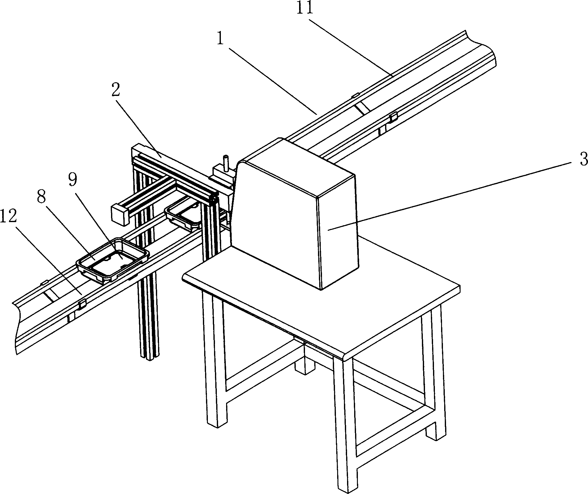
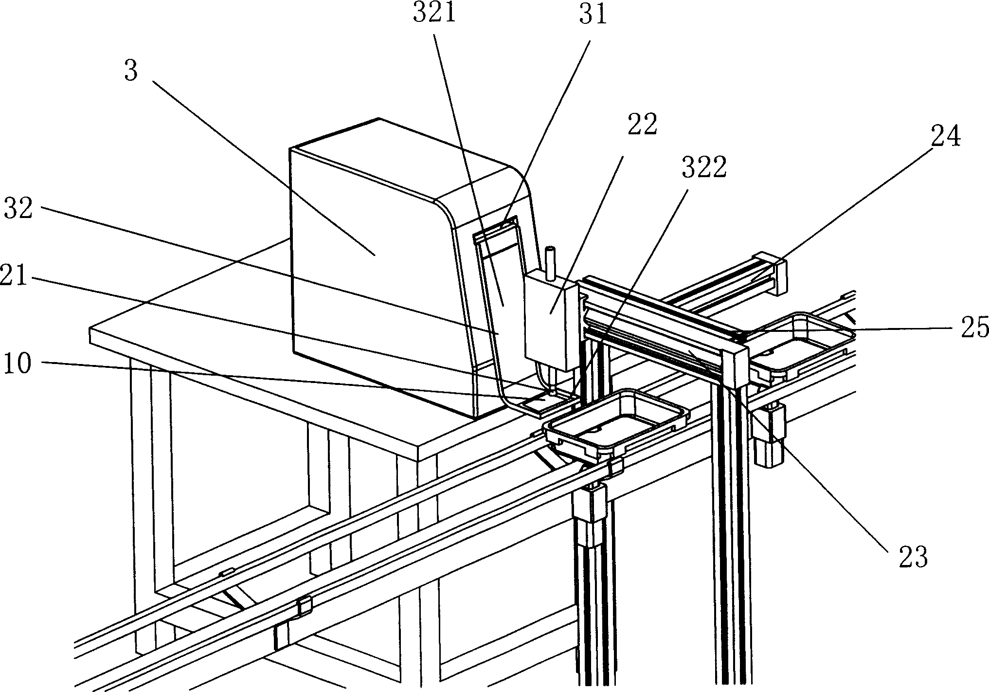
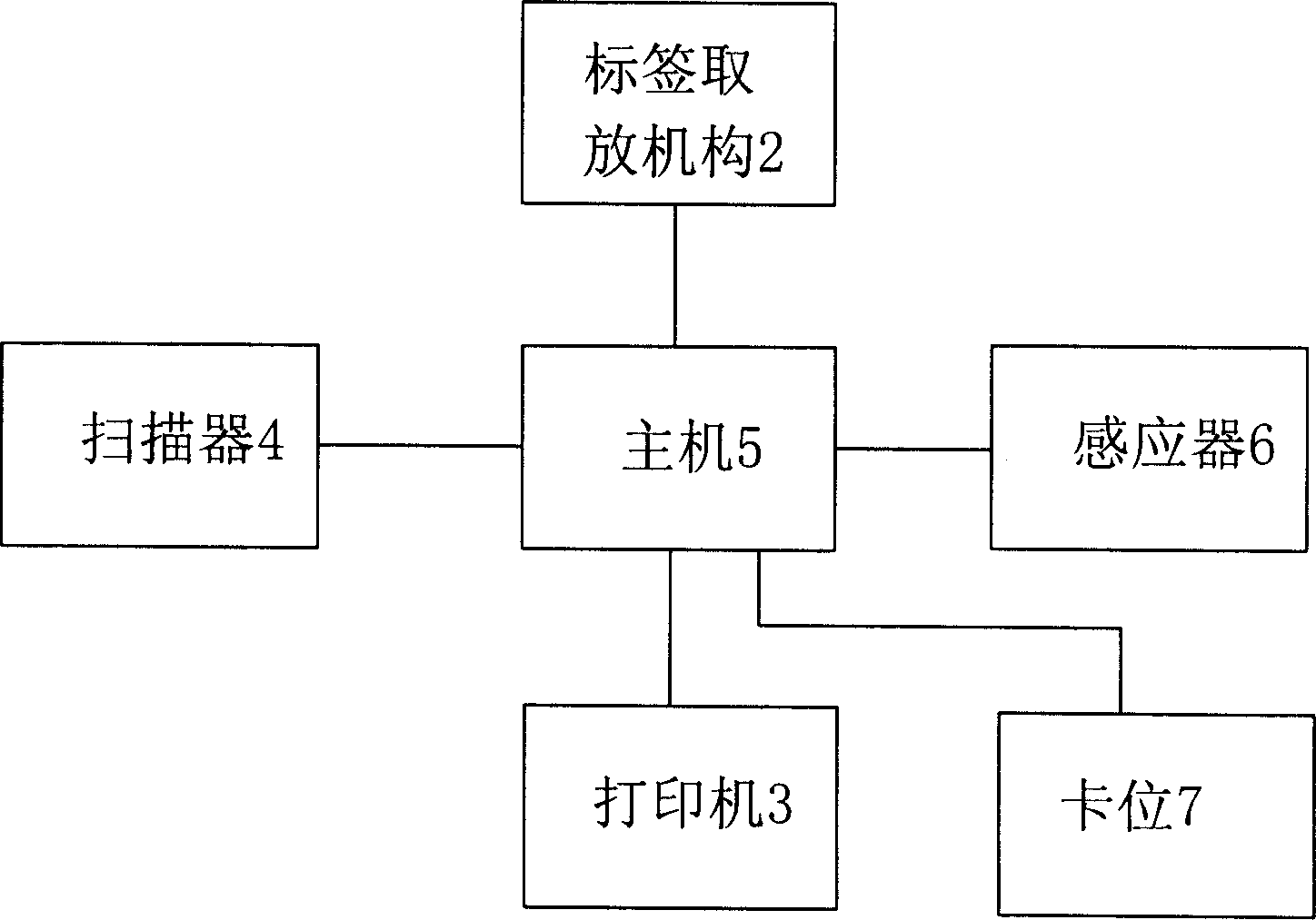
[0019] see Figure 1 to Figure 3 , The hard disk labeling system of the present invention includes a transport mechanism 1 , a label pick-and-place mechanism 2 , a printer 3 , a scanner 4 and a host computer 5 . The conveying mechanism 1 is used to convey the hard disk 9 placed in the tray 8, the label pick-and-place mechanism 2 is used to automatically pick and place the label 10, the printer 3 is used to print the label 10, and the scanner 4 is used to scan the hard disk 9 for identification For barcodes, the host computer 5 is used to coordinate and control the label pick-and-place mechanism 2 , printer 3 and scanner 4 .
[0020] Transmission mechanism 1 comprises conveyor belt support 11, conveyor belt 12 and drive motor, and this conveyor belt support 11 is fixedly arranged on the ground, and conveyor belt 12 is installed on this conveyor belt support 11, and it is driven by motor and realizes the delivery to hard disk 9.
[0021] The label pick-and-place mechanism 2 includes a suction head 21, a sliding seat 22, a guide rail 23 and a power part 24. The suction head 21 is installed on the slide seat 22, and uses the vacuum principle to automatically pick and place the label 10. The slide seat 22 is movably installed on the On the guide rail 23, the output end of the power part 24 is connected with the slide seat 22, and through the driving of the power part 24, the slide seat 22 can move along the guide rail 23 with the suction head 21, so as to realize the suction label position and Accurate positioning of label placement. In this embodiment, the suction head 21 has three positions, namely, the initial position, the suction label position for sucking the printed label, and the label placement position for accurately placing the label on the hard disk. Both the guide rail 23 and the power element 24 are fixedly installed on a bracket 25 , and the bracket 25 straddles the conveyor belt 12 , so that the suction head 21 is located at a certain height above the conveyor belt 12 . The power part 24 can adopt a motor or a cylinder.
[0022] The printing principle and basic structure of the printer 3 are as the prior art. The printer 3 is connected to the host computer 5, and an opening 31 is provided on its outer wall. The opening 31 of the printer is connected with a guide plate 32, which is roughly in the shape of an “L” and includes a first guide plate 321 attached to the outer wall of the printer 3 and a second guide plate 322 extending horizontally outward from the end of the first guide plate 321 . The printed label is output from the opening 31 of the printer, and slides along the first guide plate 321 onto the horizontal second guide plate 322 for suction by the suction head.
[0023] The scanning principle and basic structure of the scanner 4 are as in the prior art. The scanner 4 is connected to the host 5, and is used to scan the identification barcode of the hard disk 9, and transmit the collected barcode information to the host. In order to achieve a better scanning effect, the scanning head of the scanner is aligned with the position of the hard disk barcode.
[0024] Host 5 can adopt existing computer host, and this host is stored with the information database of each hard disk, and this database comprises the barcode information of each hard disk and hard disk basic information such as the hard disk model corresponding to this barcode, capacity and production date.
[0025] In addition, the present invention also includes a sensor 6 and a card position 7 arranged on the conveyor belt bracket 11 , the sensor 6 and the card position 7 are both connected to the host 5 . When the sensor 6 does not detect the tray 8 carrying the hard disk, the card position 7 is always in the non-working state, that is, the card position 7 is in the open position; when the sensor 6 senses the tray 8, the feedback signal is sent to the host 5, and the host 5 Control the work of the card position 7 to make it block the tray. Within the set time, the card position 7 has been positioning the tray 8 on the conveyor belt 12 for the scanner 4 to scan the identification barcode of the hard disk 9. After the set time is up, The clamping position 7 releases the tray 8, so that the tray 8 carries the hard disk 9 and moves with the conveyor belt 12.
[0026] Please refer to Figure 4 , the working process of the present invention is as follows: 1) The conveyor belt 12 conveys several trays 8 placed at intervals and loaded with hard disks. When the sensor 6 senses the first tray 8, it feeds back a signal to the host 5, and the host 5 controls the card Position 7 clamps this tray 8 so that it is positioned on the conveyor belt 12. During this process, other trays are still in the state of being conveyed; 2) after the first tray 8 is positioned, the scanner 4 scans the identification barcode on the side of the hard disk, And the collected barcode information is delivered to the host computer 5; 3) after receiving the barcode information, the host computer calls out the stored basic information of the hard disk corresponding to the barcode, and controls the printer 3 to print the basic information on the label. Finally, the label 10 slides from the opening 31 of the printer to the second guide plate 322 along the first guide plate 321; 4) The main engine 5 controls the power part 24 to work, so that the slide 22 moves to the top of the label 10 with the suction head 21, And suck this label by suction head 21; 5) after sucking the label, power part 24 drives slide seat 22 and suction head 21 to move to the top of hard disk 9 relative to guide rail 23, then suction head 21 puts down label and makes it fall on the hard disk.
[0027] In order to improve production efficiency, after the host receives the barcode information, it can simultaneously control the label pick-and-place mechanism and the printer to start working, so that the time A when the suction head moves from the initial position to the top of the second guide plate is the same as when the label starts to print until it falls on the second guide plate. The time B on the guide plate is the same; in addition, the card will automatically release the pallet after a certain period of time when the pallet is stuck, so that the pallet continues to move with the conveyor belt. Let the time from when the pallet is stuck and positioned to when it moves directly below the guide rail be C , assuming that the time required for the tray from being stuck to when the suction head moves to the label placement position is D, this time C is consistent with time D, that is, when the suction head picks up the label and moves to the label placement position, the tray just moves to the suction head directly below the .
[0028] When the scanner cannot scan the identification barcode of the hard disk, the host will control the scanner to scan the hard disk for three consecutive times. If the barcode is scanned once, the label will be printed and subsequent operations will be performed; if the barcode cannot be scanned three times, then The host control card releases the tray, allowing the hard disk to pass through, but does not put the label. During the three scans, the card position remained stuck on the tray. In addition, the host can also be connected with an audible and visual alarm. When the scanning of the barcode fails, the audible and visual alarm will be used to alert the operators on the production line.

PUM

no PUM

Description & Claims & Application Information

We can also present the details of the Description, Claims and Application information to help users get a comprehensive understanding of the technical details of the patent, such as background art, summary of invention, brief description of drawings, description of embodiments, and other original content. On the other hand, users can also determine the specific scope of protection of the technology through the list of claims; as well as understand the changes in the life cycle of the technology with the presentation of the patent timeline. Login to view more.

Similar technology patents

Method for Producing L-Amino Acids Using Bacteria of the Enterobacteriaceae Family

ActiveUS20060141586A1Increase productivityBacteriaHydrolasesEnterobacteriaceae bacteriumL-Arabinose
Owner:AJINOMOTO CO INC

Classification and recommendation of technical efficacy words

  • Increase productivity
  • Save human effort

Apparati, methods, and compositions for universal microbial diagnosis, detection, quantification, and specimen-targeted therapy

InactiveUS20120129794A1Increase productivityAccurate and rapid and sensitive microbial diagnosis and detection and quantificationAntibacterial agentsBiocidePopulationMolecular Targeted Therapies
Owner:DOWD SCOT E +2
Why Eureka
Try Eureka