Structure for arrangement of engine-associated vehicle components
An engine and engine room technology, which is applied to vehicle components, power plants, and power plant gas intake, etc., can solve problems such as reduced driving stability, deterioration of intake performance, and shortened overall length of intake passages.
- Summary
- Abstract
- Description
- Claims
- Application Information
AI Technical Summary
Problems solved by technology
Method used
Image
Examples
Embodiment Construction
[0055] specific implementation plan
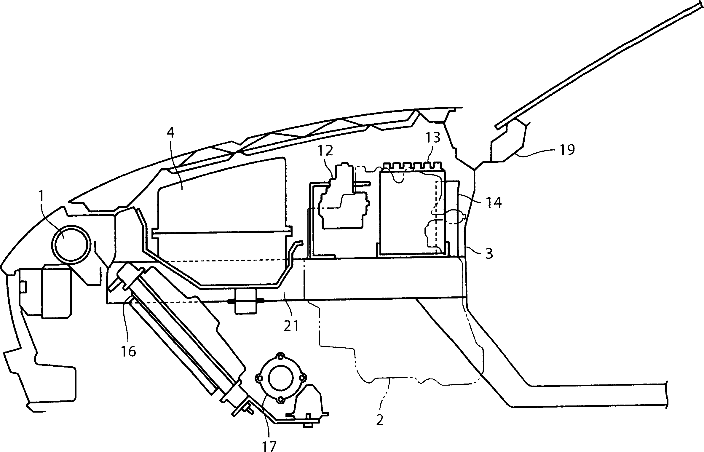
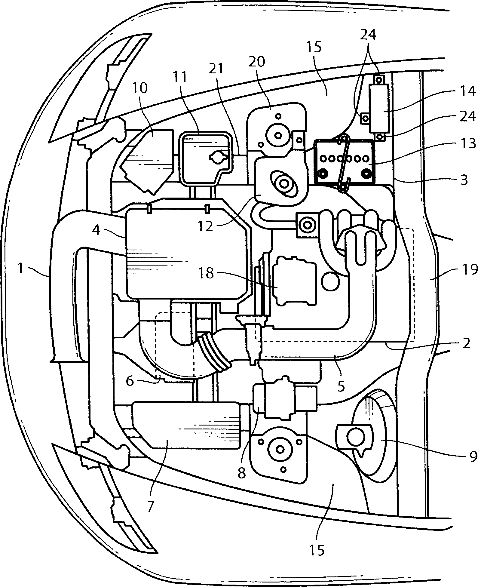
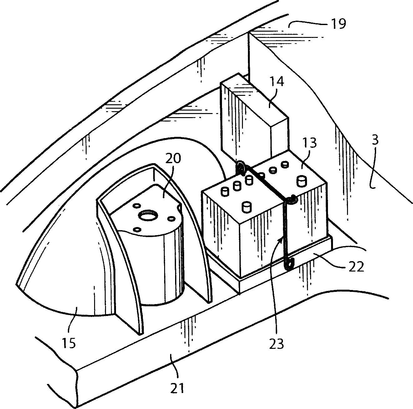
[0056] figure 1 and figure 2 It shows the internal structure of the engine room using the vehicle engine accessory installation structure which concerns on this invention. In the above-mentioned engine room, an intake air introduction part composed of a fresh air duct (fresh air duct) 1 is arranged at the front of the engine room, and at the rear of the engine room, an engine main body 2 composed of a rotary engine is arranged at the front. between a dash panel 3 and an air cleaner 4 . Thus, when the vehicle is running, the intake air sucked by the fresh air duct 1 is supplied to the engine main body 2 through the air cleaner 4 and the intake passage 5 .
[0057] On the left side of the above-mentioned engine room, the control unit 6 of the transmission mechanism (power train) and the main fuse box (mainfuse box) 7 are arranged on the side of the air cleaner 4, and between the above-mentioned control unit ...
PUM
 Abstract
Description
Claims
Application Information
 - R&D
- Intellectual Property
- Life Sciences
- Materials
- Tech Scout
- Unparalleled Data Quality
- Higher Quality Content
- 60% Fewer Hallucinations
Browse by: Latest US Patents, China's latest patents, Technical Efficacy Thesaurus, Application Domain, Technology Topic, Popular Technical Reports.
© 2025 PatSnap. All rights reserved.Legal|Privacy policy|Modern Slavery Act Transparency Statement|Sitemap|About US| Contact US: help@patsnap.com


