A fuel cell system and method for multi-manifold air supply

A fuel cell system and air supply technology, applied in fuel cells, circuits, electrical components, etc., can solve the problems of large stack consistency, inconsistent paths, and high local current density, and avoid local high or low. , The effect of reducing gas flow resistance and improving inconsistency

Active Publication Date: 2021-06-04
TONGJI UNIV
View PDF8 Cites 0 Cited by
  • Summary
  • Abstract
  • Description
  • Claims
  • Application Information

AI Technical Summary

Problems solved by technology

As the power demand of the fuel cell continues to increase, the integrated electric stack is getting bigger and bigger, which means that more single cells need to be connected in series to the electric stack, thus exacerbating the inconsistency among the single cells in the electric stack degree, increasing the possibility of fluctuations, making the local current density too high, causing hot spots or even reverse polarity, leading to failure of the stack
[0004] The oxygen supply system of the fuel cell has a great influence on the consistency of the stack
The traditional fuel cell oxygen supply system uses single-ended air supply, the humidified air is directly introduced through the inlet of the stack end cover, and then through the internal manifold on each side of the stack, although each The single-chip battery is equipped with an internal air flow field, which can better ensure that the air in the single-chip is evenly distributed, but because the air is passed through the uniform end cover opening between the single-chips, it finally reaches each single-chip battery. Inconsistent paths and uneven air volume will eventually lead to inconsistencies in the oxygen supply between the monoliths, stack fluctuations, and local current densities that are too low or too high, thus affecting the life of the overall single stack

Method used


Image

  • A fuel cell system and method for multi-manifold air supply

Examples


Embodiment

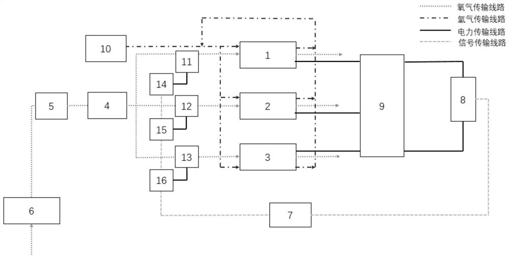
[0041] A fuel cell system fueled by multi-manifold air supply, including the following structure: an air compressor 6 that presses ambient air into it at high speed; a humidifier 5 arranged behind the air compressor 6; It is the intake main pipeline of the multi-manifold 4, and each branch manifold of the multi-manifold includes a throttle valve 11, a throttle valve 12 and a throttle valve 13, and the outlet pipe of the multi-manifold 4 is connected with each cathode end of the fuel cell; the fuel cell system It consists of a battery stack module 1, a battery stack module 2 and a battery stack module 3 in the form of a stack module; the hydrogen supply pipeline of the hydrogen storage device 10 is connected to each anode terminal of the fuel cell; one end of the electric energy conversion device 9 is connected to the fuel cell, The other end is connected to the load 8; one end of each servo motor 14, 15, 16 is connected to the throttle valve 11, 12, 13 respectively, and the oth...


PUM


Abstract

The present invention relates to a multi-manifold air-supply fuel cell system, comprising: an air compressor, used to press ambient air into the system; a humidifier, arranged behind the air compressor; a multi-manifold, the The main intake pipe of the multi-manifold is connected to the outlet of the humidifier, and throttle valves are respectively provided on each branch manifold; the fuel cell includes a plurality of battery stack modules, and the cathode terminals of each battery stack module are connected to the multi-manifold respectively. The branch manifolds are connected correspondingly; the electric energy conversion device is connected with the fuel cell at one end and the load at the other end; the control device is respectively connected with the load and each throttle valve; the hydrogen storage device, the hydrogen supply pipeline of the hydrogen storage device is connected with each The anode terminal connection of the stack module. Compared with the prior art, the invention improves the inconsistency of each module, improves the overall performance of the fuel cell system, and prolongs the service life of the fuel cell system.

Description

technical field [0001] The invention relates to a fuel cell, in particular to a multi-manifold air supply fuel cell system and method. Background technique [0002] Fuel cells are currently a promising new type of power source. Generally, hydrogen is used as fuel, as the negative electrode, and oxygen in the air is used as the positive electrode. The active substances (fuel and oxidant) of the fuel cell are continuously input while reacting, so this type of cell is actually an energy conversion device. Fuel cells are also receiving more and more attention because of their advantages such as high conversion efficiency, large capacity, high specific energy, wide power range, and no need for charging. [0003] Since the traditional fuel cell system is composed of multiple single cells in the form of bipolar plates integrated into a large electric stack in series, although this form of multi-cell integrated large electric stack has a simple structure and is easy to produce, the...

Claims


Application Information

Patent Timeline
Patent Type & Authority Patents(China)
IPC IPC(8): H01M8/04089H01M8/04111H01M8/04119H01M8/04537H01M8/04746
CPCH01M8/04089H01M8/04111H01M8/04126H01M8/04589H01M8/04753Y02E60/50
Inventor 魏学哲戴海峰熊萌王学远
Owner TONGJI UNIV
Why Eureka
Try Eureka