Portable energy storage equipment with heat dissipation wind tunnel structure

A technology for energy storage equipment and cooling fans, which is applied to mechanical equipment, parts of pumping devices for elastic fluids, non-variable pumps, etc., and can solve problems such as uneven airflow, patient discomfort, and loud fan noise

Inactive Publication Date: 2021-04-02
GUANGZHOU ALLPOWERS IND INT
View PDF0 Cites 0 Cited by
  • Summary
  • Abstract
  • Description
  • Claims
  • Application Information

AI Technical Summary

Problems solved by technology

Discrete noise is the noise generated due to the interaction between the asymmetric structure around the blade and the circumferential uneven flow field formed by the design test rotation of the blade mouth. When the working wheel rotates, the blades on the wheel hit the surrounding gas medium, causing the surrounding gas to Formed by pressure pulsation, for a certain particle in a given space, whenever the blade passes by, the pressure of the gas hitting this particle will fluctuate rapidly once, and the rotating blade will continuously pass one by one, and the pressure pulsation will continue to be generated, resulting in The airflow is very uneven, which radiates noise to the surroundings. The noise of the traditional fan is too large, and the use of the ventilator at night will cause discomfort to the patient.

Method used


Image

  • Portable energy storage equipment with heat dissipation wind tunnel structure
  • Portable energy storage equipment with heat dissipation wind tunnel structure
  • Portable energy storage equipment with heat dissipation wind tunnel structure

Examples


Embodiment Construction

[0023] The following will clearly and completely describe the technical solutions in the embodiments of the present invention with reference to the accompanying drawings in the embodiments of the present invention. Obviously, the described embodiments are only some, not all, embodiments of the present invention. Based on the embodiments of the present invention, all other embodiments obtained by persons of ordinary skill in the art without making creative efforts belong to the protection scope of the present invention.

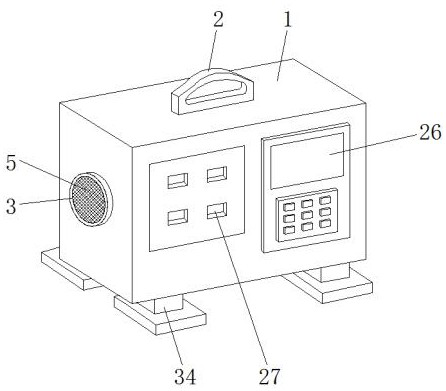
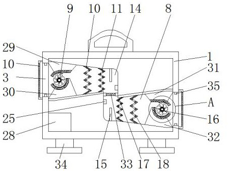
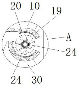
[0024] see Figure 1-5 , the present invention provides a technical solution: a portable energy storage device with a heat dissipation wind tunnel structure, including a device body 1, a handle 2 is fixedly installed on the top of the device body 1, and the two sides of the device body 1 are respectively opened There are a first vent 3 and a second vent 4, the outer sides of the first vent 3 and the second vent 4 are fixedly equipped with a dustproof net 5, an...


PUM


Abstract

The invention discloses portable energy storage equipment with a heat dissipation wind tunnel structure. The portable energy storage equipment comprises an equipment body. A handle is fixedly installed at the top of the equipment body. A first ventilation opening and a second ventilation opening are formed in the two sides of the equipment body respectively. One side of the interior of the equipment body is provided with a first air channel, and the other side of the interior of the equipment body is provided with a second air channel. A first heat dissipation fan, a first retardation plate and a second retardation plate are sequentially arranged on the inner side of the first air channel from left to right. A ventilation cavity is formed in the center of the inner side of the equipment body, the first air channel is communicated with the second air channel through the ventilation cavity, and refrigeration sheets are fixedly installed at the top of the inner side and the bottom of theinner side of the ventilation cavity. A third retardation plate, a fourth retardation plate and a second heat dissipation fan are sequentially arranged on the inner side of the second air channel fromleft to right. According to the portable energy storage equipment, heat generated in the equipment body is taken away through low-speed airflow by arranging the heat dissipation wind tunnel, so thatrapid heat dissipation is achieved; and noise generated by heat dissipation is eliminated, so that the service life of the heat dissipation fans is prolonged.

Description

technical field [0001] The invention relates to the technical field of energy storage devices, in particular to a portable energy storage device with a heat dissipation wind tunnel structure. Background technique [0002] Energy storage equipment is a device that stores electrical energy in batteries so that it can be used at any time, which can bring convenience to people. [0003] A wind tunnel is a windy test environment that produces artificial simulations of different wind speeds, temperatures, and flows, and is used to study the aerodynamic effects of air flowing through objects. Wind tunnels are divided into vertical wind tunnels, horizontal wind tunnels, or vertical and horizontal wind tunnels according to the direction. According to the different test wind speeds, they can be divided into supersonic wind tunnels, sonic wind tunnels, subsonic wind tunnels, and low-speed wind tunnels. According to the application of the wind tunnel, it can be divided into a wind tunn...

Claims


Application Information

Patent Timeline
Patent Type & Authority Applications(China)
IPC IPC(8): F04D25/08F04D25/16F04D29/00F04D29/059F04D29/42F04D29/58F04D29/66F04D29/70
CPCF04D25/08F04D25/166F04D29/002F04D29/059F04D29/4226F04D29/582F04D29/663F04D29/703
Inventor 钟小军
Owner GUANGZHOU ALLPOWERS IND INT
Why Eureka
Try Eureka