Cylindrical cell and manufacturing method thereof

A technology of cylindrical battery and manufacturing method, applied in the direction of battery pack components, circuits, electrical components, etc., capable of solving problems such as high connection resistance, battery voltage drop, breakage, etc.

Active Publication Date: 2006-10-04
PANASONIC CORP
View PDF1 Cites 6 Cited by
  • Summary
  • Abstract
  • Description
  • Claims
  • Application Information

AI Technical Summary

Problems solved by technology

[0005] However, in the above-mentioned conventional structure, since the metal case and the negative electrode current collector are connected by only one point of welding, there is a problem that the connection resistance between the metal case and the current collector is high.
For example, when discharging with a large current of 100A, there is a problem that the voltage of the battery drops rapidly due to the high resistance of the welded part of the metal case and the negative electrode current collector.
In addition, as in Figure 12 When the tongue-shaped connecting piece 22 is welded to the metal shell as shown, the conduction resistance of the tongue-shaped connecting piece 22 itself is large, and the tongue-shaped connecting piece 22 may melt when a large current flows. And the problem of breaking
In addition, as disclosed in Japanese Patent Application Laid-Open No. 2000-106165, when the welding protrusion at the center of the bottom surface of the metal case is welded to the negative electrode current collector, if the internal pressure of the battery increases due to the overcharged state of the battery, etc., the metal The bottom surface of the case expands, and the negative electrode current collector is also deformed in the same way, and the welded part with the negative electrode plate may be peeled off, which may increase the resistance of the battery.

Method used


Image

  • Cylindrical cell and manufacturing method thereof
  • Cylindrical cell and manufacturing method thereof
  • Cylindrical cell and manufacturing method thereof

Examples


no. 1 Embodiment approach

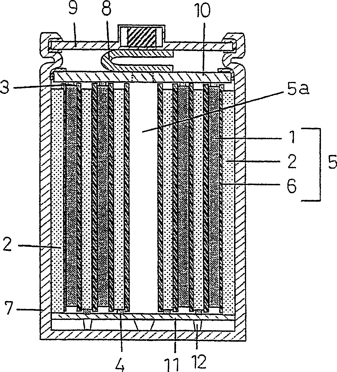
[0028] First, refer to Figure 1 to Figure 7 The cylindrical battery and its manufacturing method according to the first embodiment of the present invention will be described.

[0029] figure 1 It is a schematic sectional view of the cylindrical battery of this embodiment. exist figure 1Among them, the electrode plate group 5 of the cylindrical battery is formed by winding them in a spiral shape with the strip-shaped separator 6 sandwiched between the strip-shaped positive electrode plate 1 and the strip-shaped negative electrode plate 2 . The core material 3 of the positive electrode plate 1 protrudes above the electrode plate group 5 , and the core material 4 of the negative electrode plate 2 protrudes below the electrode plate group 5 . On the protruding part of the core material 3 of the positive electrode plate 1 protruding above the electrode plate group 5, the positive electrode current collector 10 is welded, and on the protruding part of the core material 4 of t...

no. 2 Embodiment approach

[0040] Next, refer to Figure 8 ~ Figure 10 A cylindrical battery and its manufacturing method according to the second embodiment of the present invention will be described. In addition, the same reference numerals are assigned to the same components as those in the first embodiment, and description thereof will be omitted, and only differences will be mainly described.

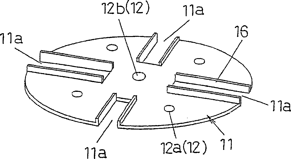
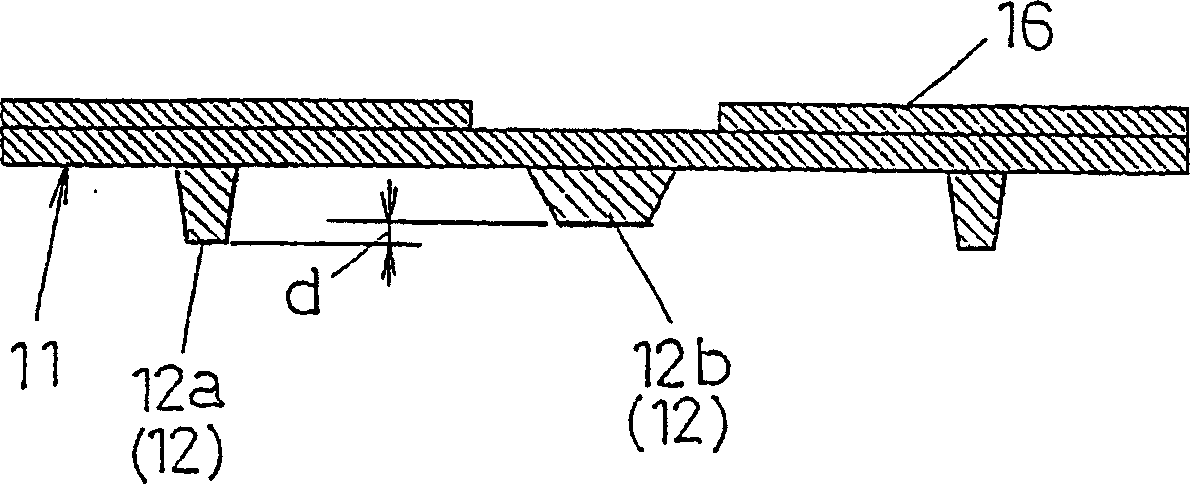
[0041] In the above-mentioned first embodiment, the protrusions 12a, 12b are protruded from the lower surface of the negative electrode current collector 11, and are welded to the inner bottom surface of the metal case 7 via the protrusions 12a, 12b. However, in this embodiment, Protrusions 15 ( 15 a , 15 b ) are protruded from the inner bottom surface of the metal case 7 , and are welded to the planar lower surface of the negative electrode current collector 11 .

[0042] exist Figure 8 Among them, on the bottom surface of the metal shell 7, a plurality of protrusions 15a are protruded upward in the area ...


PUM

PropertyMeasurementUnit
Diameteraaaaaaaaaa
Heightaaaaaaaaaa
Thicknessaaaaaaaaaa

Abstract

A cylindrical cell includes; a group of electrode plates (5); a positive electrode collector (10) welded to a core protrusion of the positive electrode in the group of electrode plates (5); a negative electrode collector (11) having a plurality of projections (12) protruding to the lower surface and having the upper surface welded to a core protrusion of the negative electrode in the group of electrode plates (5); a metal case (7) containing the group of electrode plates(5) having the welded positive / negative electrode collectors (10, 11) with the negative electrode collector (11) downward and the projections (12) of the negative electrode (11) welded to the inner bottom surface; electrolytic liquid contained in the metal case (7); and a sealing body (9) electrically insulated from the metal case (7) and sealing the upper portion of the metal case (7). The projections (12) of the negative electrode collector (11) are arranged at a plurality of positions in the region between the portion opposing to the hollow cylindrical portion (5a) and a peripheral portion. Thus, the cylindrical cell can have a high resistance against a large current discharge and a high metal case pressure.

Description

technical field [0001] The present invention relates to a cylindrical battery with a spirally wound electrode plate group and a manufacturing method thereof. Background technique [0002] There are many kinds of cylindrical batteries, and nickel-cadmium batteries and nickel-metal hydride batteries are representative. Since these cylindrical batteries are highly reliable and easy to maintain, they are widely used in various applications such as power supplies for mobile phones and notebook computers. Furthermore, in recent years, the development of cylindrical batteries suitable for large current discharge has been demanded as a power source for electric assist bicycles, lawn mowers, and even electric vehicles. [0003] This type of cylindrical battery for large current is stacked with a strip-shaped positive electrode plate and negative electrode plate sandwiching a separator for isolation, the whole is wound in a spiral shape to form an electrode plate group, and the elect...

Claims


Application Information

Patent Timeline
IPC IPC(8): H01M2/26H01M50/533H01M50/536H01M50/538
CPCY02E60/12Y02E60/10
Inventor 尾藤诚二米山聪加藤正彦
Owner PANASONIC CORP
Why Eureka
Try Eureka