Selective metal drop size spray-deposition method
A technology of spray deposition and metal droplets, which is applied in the field of spray deposition, can solve problems such as inability to obtain high-quality ingots, and achieve high-quality effects that are conducive to popularization and application
- Summary
- Abstract
- Description
- Claims
- Application Information
AI Technical Summary
Benefits of technology
Problems solved by technology
Method used
Image
Examples
specific Embodiment approach 1
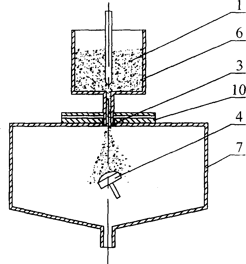
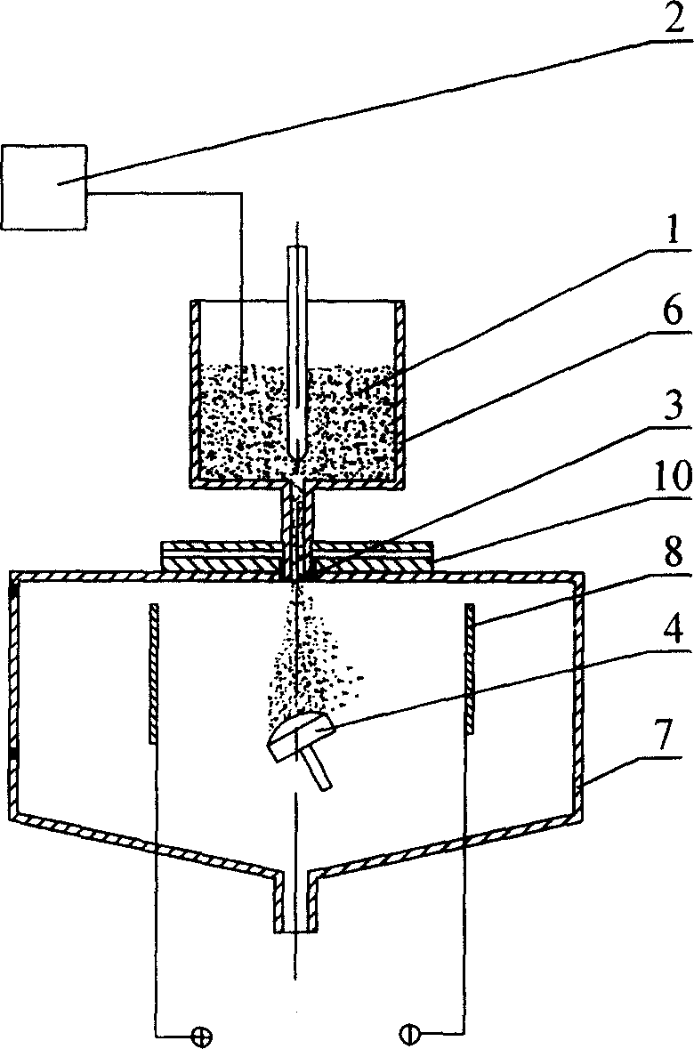
[0007] Embodiment 1: This embodiment is a spray deposition method with optional metal droplet size. The existing spray deposition method is to fill the molten metal 1 in the crucible 6, with reference to figure 1 , the injection cavity 7 is arranged below the crucible 6, the molten metal 1 is sprayed out through the nozzle 3 at the lower end of the crucible, atomized by the atomization system 10 and then sprayed onto the billet 4' for deposition. Since the existing spraying method cannot separate the metal droplets of different particle sizes, the metal particles of different sizes sprayed from the nozzle 3 after atomization can only be sprayed on the billet without selection. Affects the deposition quality, so this embodiment connects the molten metal 1 in the existing spray deposition equipment to the charge source 2, the purpose is to charge the molten metal 1, and then charge the molten metal 1 in the molten metal nozzle of the existing spray deposition equipment An elect...
specific Embodiment approach 2
[0008] Embodiment 2: The difference between this embodiment and Embodiment 1 is that the setting of the electric field is that one metal plate 8 is connected to the positive pole of the power supply, the other metal plate is connected to the ground, and the metal plate is connected to the ground instead of the negative pole. The connection has the advantages of being convenient, simple and easy to operate.
specific Embodiment approach 3
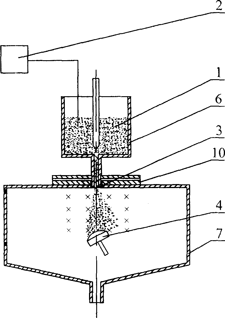
[0009] Embodiment 3: This embodiment differs from Embodiments 1 and 2 in that a magnetic field is used instead of an electric field. The molten metal 1 in the spray deposition equipment is connected to the charge source 2, referring to image 3 , A magnetic field is set between the molten metal nozzle 3 and the ingot 4, and the direction of the magnetic field is perpendicular to the extension line of the molten metal nozzle 3 axis. The magnet described in this embodiment is a permanent magnet, refer to image 3 , Figure 8 , the N pole and S pole of the permanent magnet are respectively arranged on both sides of the 3-axis extension line of the molten metal nozzle, so that a magnetic field is generated between the N pole and the S pole, and the magnetic field force will have an impact on the ejected charged metal particles Make it deflect, so as to achieve the same purpose of separating metal particles with different particle sizes as in the first embodiment. Similarly, in ...
PUM
 Abstract
Description
Claims
Application Information
 - R&D
- Intellectual Property
- Life Sciences
- Materials
- Tech Scout
- Unparalleled Data Quality
- Higher Quality Content
- 60% Fewer Hallucinations
Browse by: Latest US Patents, China's latest patents, Technical Efficacy Thesaurus, Application Domain, Technology Topic, Popular Technical Reports.
© 2025 PatSnap. All rights reserved.Legal|Privacy policy|Modern Slavery Act Transparency Statement|Sitemap|About US| Contact US: help@patsnap.com


