Fluid ejection devices, medical equipment

A technology of fluid jetting and fluid, which is applied in the direction of fluid jetting scalpel, medical science, surgery, etc., and can solve problems such as unresection or incision

Active Publication Date: 2015-08-19
SEIKO EPSON CORP
View PDF4 Cites 0 Cited by
  • Summary
  • Abstract
  • Description
  • Claims
  • Application Information

AI Technical Summary

Problems solved by technology

Conversely, in the case of resection of a specific narrow part, when the hand shakes, the ejected fluid may be sprayed to a part other than the part intended to be resected, and the resection may not be performed as desired by the operator. subject

Method used


Image

  • Fluid ejection devices, medical equipment
  • Fluid ejection devices, medical equipment
  • Fluid ejection devices, medical equipment

Examples


Embodiment approach 1

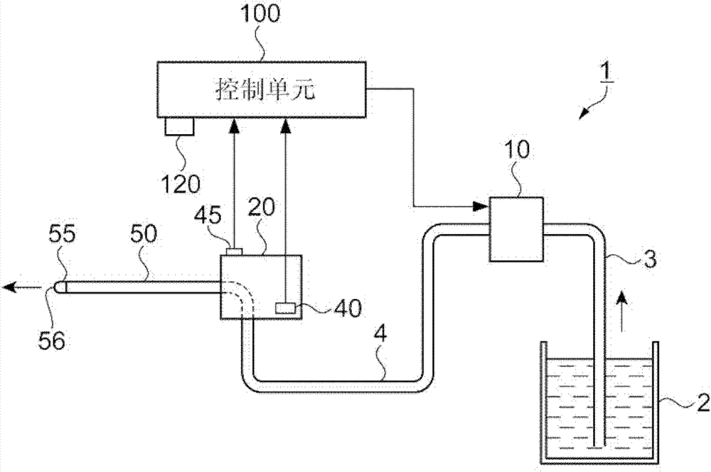
[0040] figure 1 It is a configuration diagram showing the outline of the fluid ejection device 1 of the first embodiment. in figure 1 Here, the fluid ejection device 1 is composed of the following parts: a fluid supply unit 10 that sucks fluid from a fluid container 2 containing fluid via a first connecting pipe 3; a fluid ejection pipe 50 that ejects the fluid supplied from the fluid supply unit 10; 2 A connecting pipe 4, which connects the fluid injection pipe 50 and the fluid supply unit 10; and a control unit 100, which controls the injection of fluid.

[0041] Here, the fluid supply unit 10 is a pump, and the form of the pump is not particularly limited. At the end of the fluid ejection tube 50, a nozzle 55 with a fluid ejection opening 56 with a reduced diameter of the flow path is inserted. The nozzle 55 further increases the supply pressure of the fluid supply unit 10, enabling high-speed ejection from the fluid ejection opening 56 . Therefore, the fluid ejection tube 5...

Embodiment approach 2

[0064] Next, a fluid ejection device 1 and a fluid ejection control method of Embodiment 2 will be described. In contrast to the case where the fluid injection in the first embodiment described above is a continuous flow, the feature of the second embodiment is a pulse flow.

[0065] Figure 5 It is a configuration diagram showing the outline of the fluid ejection device 1 of the second embodiment. in Figure 5 Here, the fluid ejection device 1 is composed of the following parts: a fluid supply unit 10 that sucks fluid from a fluid container 2 containing fluid via a first connecting pipe 3; and a pulsation generating part 30 that pulsates the fluid supplied from the fluid supply unit 10 The fluid ejection pipe 50, which communicates with the pulsation generating portion 30; the second connecting pipe 4, which connects the fluid supply unit 10 and the pulsation generating portion 30; and the control unit 100, which controls the ejection of the fluid.

[0066] Here, the fluid supply...

Embodiment approach 3

[0100] Next, a fluid ejection device of Embodiment 3 will be described. In the second embodiment described above, the injection of the fluid is controlled based on the signal of the pulse injection switch 46, the information of the injection pattern, and the detection signal of the acceleration sensor 40. In contrast, the third embodiment is different in that it has an information output unit. The output of the information output unit is controlled by the information of the injection mode and the detection signal (operation acceleration) of the acceleration sensor 40. Therefore, the description will focus on the differences.

[0101] Picture 11 It is a configuration explanatory diagram showing the main configuration of the control unit 100 of the third embodiment. In addition, parts having the same functions as those in the second embodiment are given the same reference numerals, and their description is omitted.

[0102] The control unit 100 has: a control circuit 110 that perf...


PUM


Abstract

A fluid ejection device for ejecting a fluid to incise or excise a target includes: a fluid supplying unit which supplies the fluid; an operation unit to which the fluid supplied from the fluid supplying unit continues; a fluid ejection tube which ejects the fluid continuing to the operation unit; an ejection mode selecting unit which allows a predetermined ejection mode to be selected; an acceleration sensor which detects an operation acceleration of the operation unit; and a controller which controls ejection of the fluid, using a preset acceleration that is set on the basis of the ejection mode that is selected, and the operation acceleration detected by the acceleration sensor.

Description

Technical field [0001] The present invention relates to a fluid ejection device, a fluid ejection method, and medical equipment using the fluid ejection device. Background technique [0002] Conventionally, there has been known a fluid jet cutting control system that jets pressurized fluid to cut tissues. In this fluid ejection cutoff control system, the ejection force of the fluid is controlled by the output (pressure) of the pump. As the pressure control method of this pump, there is a method of adding a sensor that monitors the flow rate and pressure of the pump or end effector, and a method of inputting an output change command to the console by the operator using a foot switch (for example, refer to Patent Document 1. ). [0003] [Patent Document 1] JP 2006-198409 A [0004] According to Patent Document 1 as described above, when the end effector is held by hand to excise the targeted tissue, although the ejection force can be controlled, the degree of excision varies with th...

Claims


Application Information

Patent Timeline
Patent Type & Authority Patents(China)
IPC IPC(8): A61B17/3203
CPCA61B19/46A61B2019/464A61B17/3203A61B2017/00154A61B2017/00075A61B2090/064A61B90/06
Inventor 小岛英挥
Owner SEIKO EPSON CORP
Why Eureka
Try Eureka