Measuring methods for use on machine tools

A technology for machine tools and workpieces, which is applied in the field of machine tools to measure workpieces, and can solve problems such as impossible and difficult

Active Publication Date: 2006-11-01
RENISHAW PLC
View PDF2 Cites 21 Cited by
  • Summary
  • Abstract
  • Description
  • Claims
  • Application Information

AI Technical Summary

Problems solved by technology

However, such modifications are different for different controllers, which is not easy or even possible

Method used


Image

  • Measuring methods for use on machine tools
  • Measuring methods for use on machine tools
  • Measuring methods for use on machine tools

Examples


Embodiment Construction

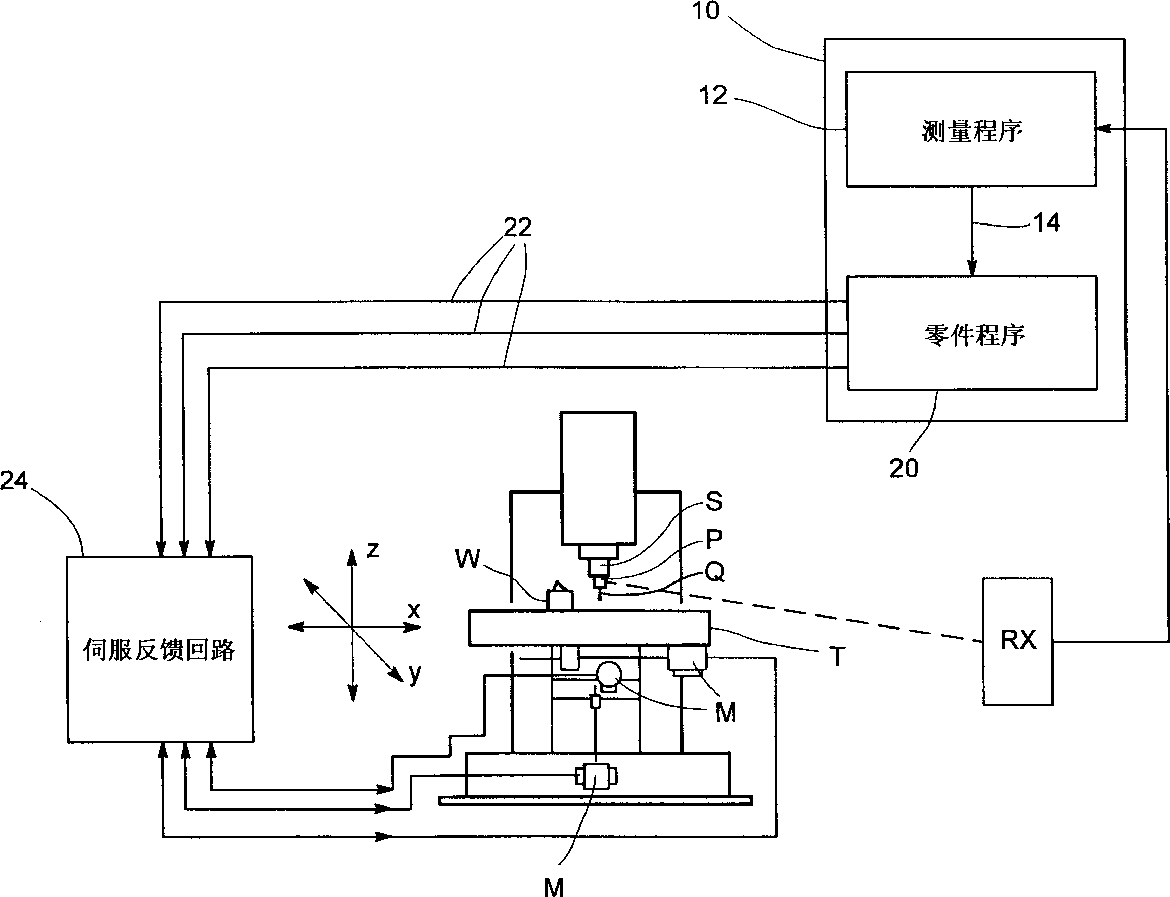
[0024] figure 1 A typical machine tool is shown, which includes a table T and a shaft S, which can be driven by a motor M to move relative to each other along the x, y, z directions. This example shows that the motor M drives the table while the shaft remains stationary. However, the invention is equally applicable to other machine tool arrangements, for example where the relative movement takes place between a stationary machine table or base and a moving axis.

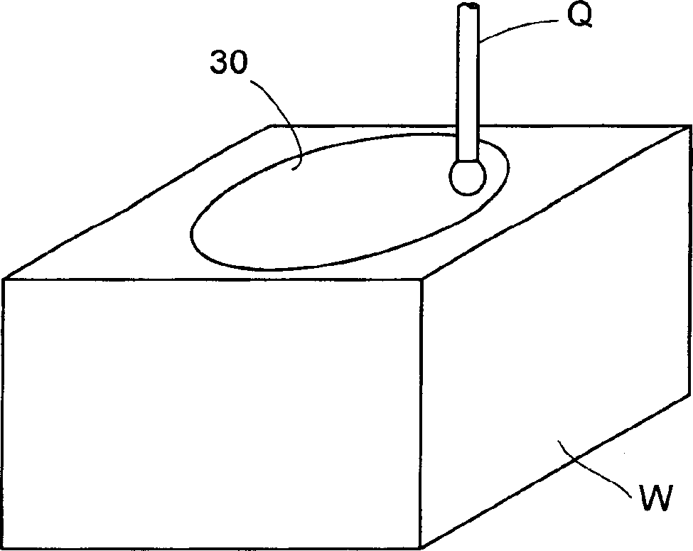
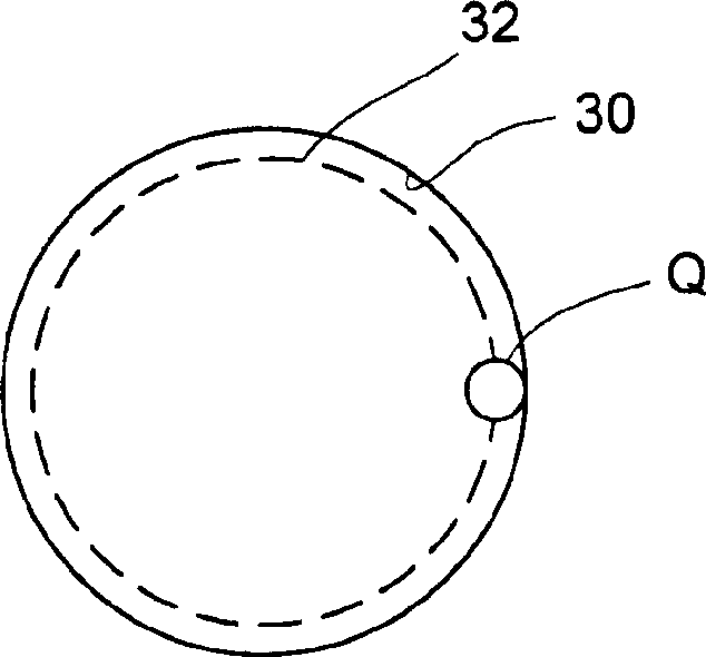
[0025] Normally, the cutting tool would be mounted on said axis S, but figure 1 Instead, an analog or scanning probe P is shown mounted on the axis for performing scanning measurements on the workpiece W mounted on the table T. The probe P has a deflectable stylus Q for contacting the surface of the workpiece W, and a sensor (not shown) of the probe P measures the position of the stylus Q in three directions of x, y, and z. Skewing, such as described in US Patent No. 4,084,323 (herein incorporated by reference). ...


PUM


Abstract

On a machine tool, a program (12) receives data from a scanning or analogue probe P, measuring a feature of a workpiece W. This data is combined with assumed machine position data during the scanning movement. This avoids having to break into the servo feedback loop (24) to get actual measured machine position data. The assumed machine position data can be derived from a part program (20) which controls the scanning movement. Several ways are described for compensating for errors between the assumed machine position values and the actual values.

Description

technical field [0001] The invention relates to the measurement of workpieces with machine tools, especially scanning measurement. Background technique [0002] It is known to mount measuring probes on machine axes that move relative to the workpiece in order to measure workpieces. In practice, the probe is typically a contact trigger probe, such as that described in US Patent No. 4,153,998 (McMurty), which generates a trigger signal when the probe stylus touches the workpiece surface. This trigger signal is input to the numerical control of the machine tool in a so-called "jump mode". As feedback, the controller takes an instantaneous read of the machine tool position (ie the position of the axes and the probe relative to the machine). This is done by a measuring device of the machine such as an encoder or decoder providing position feedback information for the machine motion servo control loop. [0003] In the field of Coordinate Measuring Machines (CMM), it is known to...

Claims


Application Information

Patent Timeline
Patent Type & Authority Applications(China)
IPC IPC(8): G01B21/04G05B19/19
CPCG01B21/04G05B19/19G05B2219/36503G05B2219/37097G05B2219/50049G05B2219/50063
Inventor 杰弗里·麦克法兰
Owner RENISHAW PLC
Why Eureka
Try Eureka