Backward flowing preventing device for air blowoff duct

A technology for air exhaust and anti-backflow, which is applied to vertical pipes, building components, buildings, etc., and can solve the problems of insufficient suction effect and other problems

Active Publication Date: 2006-11-15
HENAN WUJIAN CONSTR GRP +1
View PDF1 Cites 0 Cited by
  • Summary
  • Abstract
  • Description
  • Claims
  • Application Information

AI Technical Summary

Problems solved by technology

[0002] Chinese Patent Publication No. CN1693627A discloses an anti-backflow part of a kind of exhaust duct whose application number is 200510070394.9. This technology still has the following deficiencies: when high-rise residential buildings only have the range hood at the bottom to open and use, the exhaust duct at the top The speed change hole of the anti-backflow component has an unsatisfactory suction effect on its adjacent air induction channel

Method used


Image

  • Backward flowing preventing device for air blowoff duct
  • Backward flowing preventing device for air blowoff duct
  • Backward flowing preventing device for air blowoff duct

Examples


Embodiment Construction

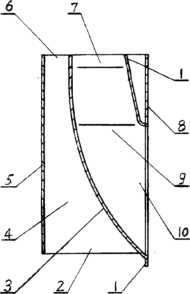
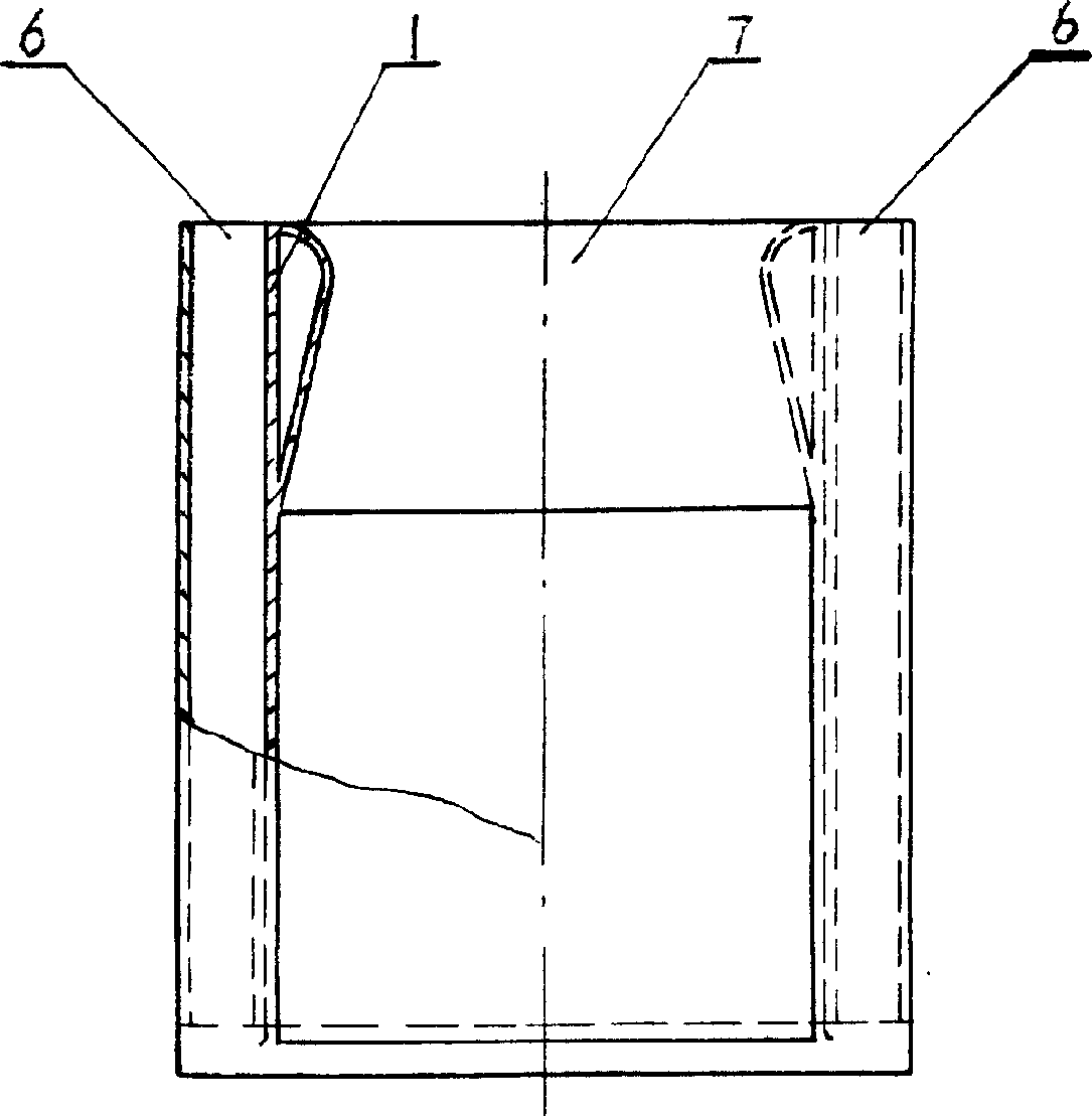
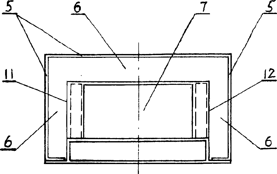
[0010] Such as Figure 1-3 As shown, the present invention includes a housing 1 and a speed change plate 5 arranged outside the housing 1. The outer shape of the housing 1 is a cone with a thin bottom and a thick top. The housing 1 includes an air inlet side 8 and a speed change side 3 and The left side 11 and the right side 12 are provided with an air induction channel 9 in the housing 1, the air inlet 10 of the air induction channel is arranged on the air inlet side 8, and the air outlet 7 is on the top surface of the housing. The cross-section of the air outlet 7 facing upwards gradually decreases, and the cross-section at the air outlet is the smallest, and the whole air-inducing channel is just like a pot mouth. The speed change plate 5 is arranged around the outside of the speed change side 3, the left side 11, and the right side 12, and a lower air inlet 2 is formed between the speed change plate 5 and the speed change side 3, the left side 11, and the right side 12. T...


PUM


Abstract

The present invention relates to a backflow-resisting device used in the exhaust duct of kitchen and toilet. Said backflow-resisting device includes a shell body and a speed-changing plate placed around the exterior of said shell body, and in the interior of said shell body an induced draft channel whose inlet is large and cutlet is small is placed, and the speed-changing holes formed by utilizing shell body and speed-changing plate are positioned outside of the induced draft channel. Said invention also provides its concrete working principle, its structure is simple and can obtain good exhaust effect.

Description

Technical field: [0001] The invention relates to an anti-backflow device used in an air exhaust channel in a kitchen and toilet. Background technique: [0002] Chinese Patent Publication No. CN1693627A discloses an anti-backflow part of a kind of exhaust duct whose application number is 200510070394.9. This technology still has the following deficiencies: when high-rise residential buildings only have the range hood at the bottom to open and use, the exhaust duct at the top The speed change hole of the anti-backflow component has an unsatisfactory suction effect on its adjacent air induction channel. Invention content: [0003] The purpose of the present invention is to overcome the deficiencies in the prior art and provide a speed change plate that is arranged around the outside of the shift side, left side, and right side of the housing, and the formed speed change holes connect the air outlet of the housing air-introduction channel to the air outlet. Surrounded by an a...

Claims


Application Information

Patent Timeline
Patent Type & Authority Applications(China)
IPC IPC(8): E04F17/04
Inventor 李振文吴丽珊吴汉木
Owner HENAN WUJIAN CONSTR GRP
Why Eureka
Try Eureka